Fire Alarm Control Panel IQ8Control C / M
108 FB 798951.10.GB0 / 04.15
11 Diagnostic display
11.1 Diagnostic display IQ8Control C/M
The diagnostic display enables, e.g. a fast check of the power supply values of this FACP Panel IQ8Control C/M
for service and maintenance work. In the panel display, a diagnostic field with individual measured values (analog
measurement channels) which are automatically determined by the control panel is displayed.
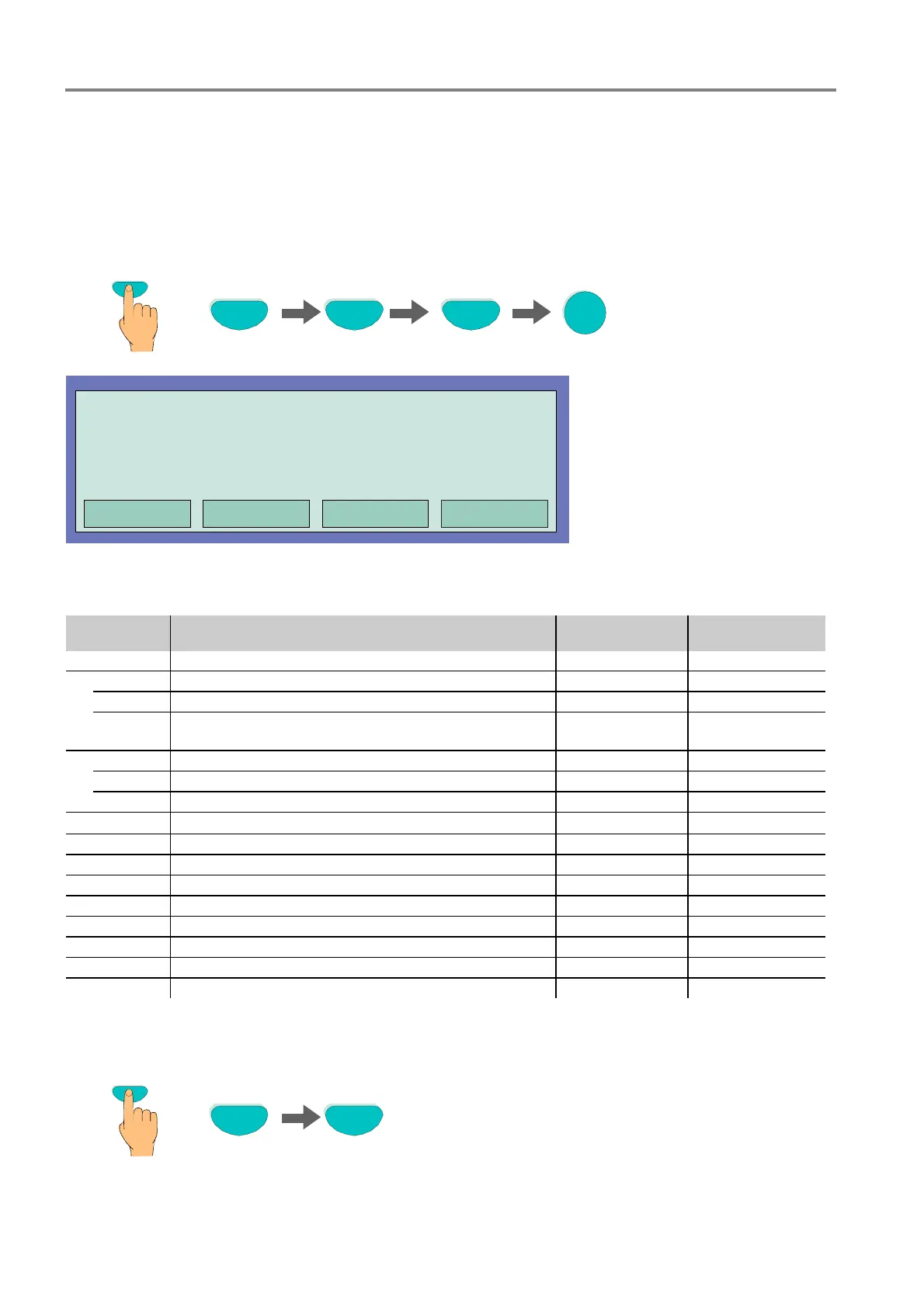
Key press sequence for switching on the diagnostic display Test-Test-F4-3
Press key
F4
Test
3
Test
Analog 0
Analog 4
Analog 8
Analog 12
Analog 1
Analog 5
Analog 9
Analog 13
Analog 2
Analog 6
Analog 10
Analog 14
Analog 3
Analog 7
Analog 11
Analog 15
Fig. 99: Panel power supply values
The display is structured in a matrix for a quick survey. The significance of the individual analog channels see
table below.
Analog
channel
Description Voltage limits Range of values
Analog 0 Micro module on the Basic module ---* ---*
1*
Analog 1 Micro module plug 1 on the Extension module ---* ---*
Analog 2 Micro module plug 2 on the Extension module ---* ---*
Analog 3 Micro module plug 3 on the Extension module or Micro
module plug on the peripheral module
---* ---*
2*
Analog 4 Micro module plug 1 on the Extension module ---* ---*
Analog 5 Micro module plug 2 on the Extension module ---* ---*
Analog 6 Micro module plug 3 on the Extension module ---* ---*
Analog 7 Test channel
2,5 V
2 %
120 to 135
Analog 8 Power supply, Secondary voltage 12V DC 10V to 15V 82 to 152
Analog 9 Battery _1 10V to 14V 121 to 168
Analog 10 Battery _2 10V to 14V 121 to 168
Analog 11 Ub
extern
12V DC 10V to 15V 82 to 152
Analog 12 ULinie + 27,5V oder +42 Volt 26V to 29V 108 to 149
Analog 13 Ground fault 10,5V to 14,6V 60 to 120
Analog 14 Monitoring IN1 (e. g. External power supply) 4 V 65 to 255
Analog 15 Monitoring IN2 (e. g. External power supply) 4 V 65 to 255
* = values relating to the fitted micro module
1* = System connector 1
2* = System connector 2
Switch off the diagnostic display with function key F1 or F4
Press key
F1 F4

 Loading...


