Fire Alarm Control Panel IQ8Control C / M
FB 798951.10.GB0 / 04.15 29
5.6 Operating module / Housing door
The operating module/the housing door is installed by the manufacturer on the front housing part. If required for
dismantling, loosen the 4 fixing screws and remove the front part of the housing.
Depending on the configuration, e.g. with or without an installed printer or an individual zone display, deviation
from the illustration here is possible.
123
456
789
0
8
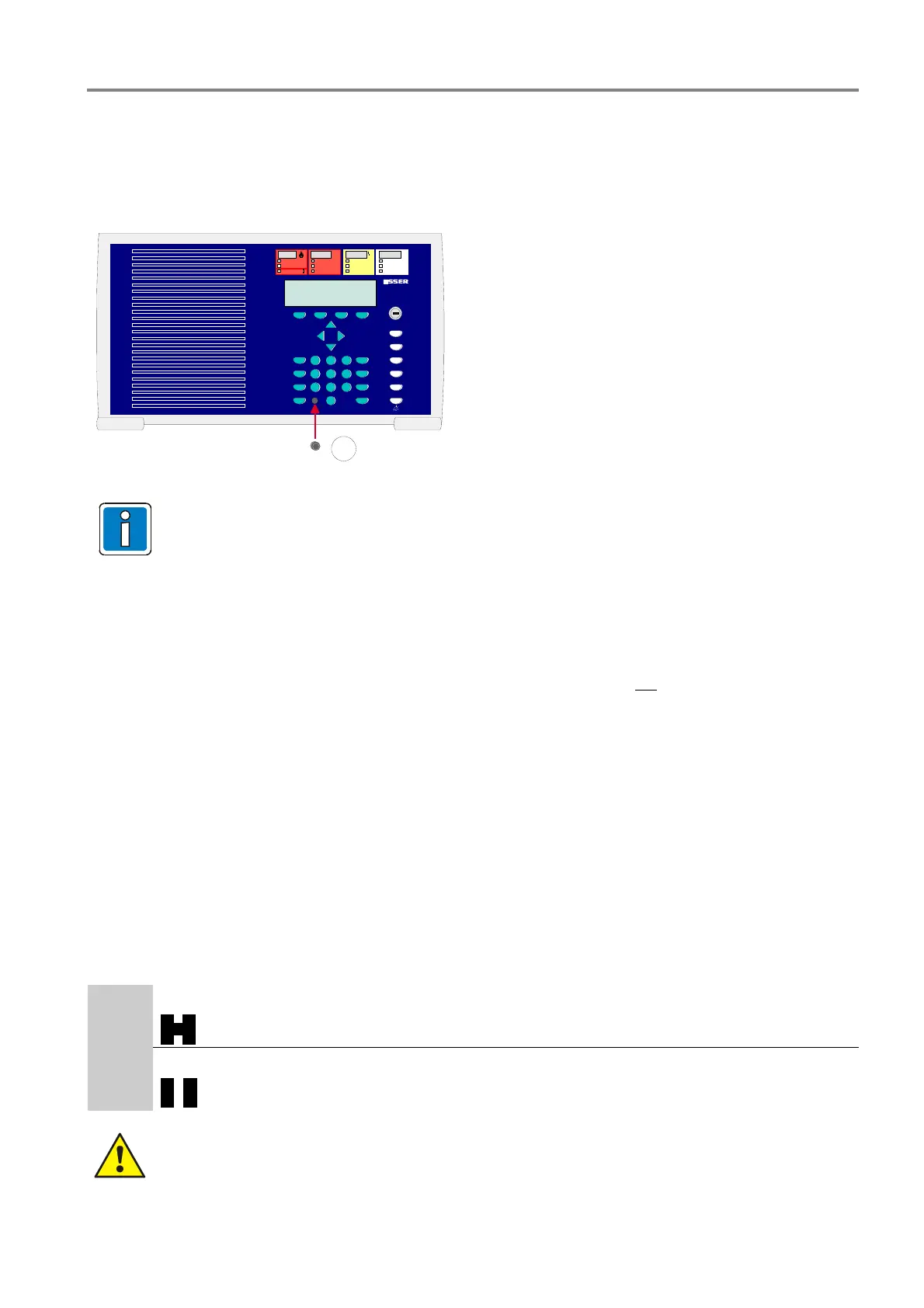
For correct ESD protection it is highly
recommended to insert the dummy plug
(insert pack) of the programming interface
plug into front of the operation panel.
Fig. 21: Operating module / Housing door
The operating module is not required for programming the FACP IQ8Control. The service PC can
also be directly connected to the programming connector of the Basic module.
The operating module can be fully simulated with all functions on the service PC. The service and
programming software tools 8000/ReCo are required for this.
Opening
The front door key is always required to open the housing front.
It can be opened with the key vertical
Closing
To close the front door, the lock must be in the horizontal position. The key is not required. The front door can
simply be pushed closed and engaged in the snap-type fastener.
Example: Housing IQ8Control C
1. Place front frame with integrated door carefully onto the back box.
Take care to ensure that no cables are pinched or damaged when installing or removing the assembly.
2. Insert the four screws between the back box and the front frame and tighten carefully.
3. Insert housing contact in the upper place of the housing with the contact tab downwards. The contact is
connected to the Basic module by factory settings and may be removed for service or maintenance work.
4. Connect the ribbon cable of the operation panel to the corresponding connector on the Basic module.
5. This completes assembly of the housing
5.7 Panel buzzer
If required the internal panel buzzer may be disabled with the solder jumper BR2 on the rear side of the operating
panel PCB.
BR2
BR2
closed, buzzer enabled (factory setting)
BR2
open, buzzer disabled
If the buzzer is permanently disabled (BR2 open), the transmission of this audible warning signal to
must be ensured (e.g. by indicating this condition at a panel within the essernet
®
)!

 Loading...


