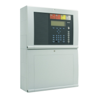
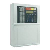
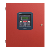
Fire Alarm Control Panel IQ8Control C / M
FB 798951.10.GB0 / 04.15 3
Table of contents
1
General / Application .................................................................................................................................................. 5
2 Standards and guidelines .......................................................................................................................................... 7
2.1 Approvals .............................................................................................................................................................. 7
3 Transport damage inspection .................................................................................................................................... 8
4 Configuration variants .............................................................................................................................................. 10
4.1 Special configuration – Swiss option
CH
....................................................................................................... 11
4.2 FACP IQ8Control C ........................................................................................................................................... 12
4.3 FACP IQ8Control M........................................................................................................................................... 14
4.4 Definition of the Primary loop number .............................................................................................................. 19
5 Assembly and installation information .................................................................................................................... 21
5.1 Maintenance / Service ....................................................................................................................................... 22
5.2 Assembling the wall housing ............................................................................................................................. 23
5.3 Fitting the panel to the mounting surface ......................................................................................................... 24
5.4 Cable glands ...................................................................................................................................................... 27
5.5 Connection between the housings ................................................................................................................... 28
5.6 Operating module / Housing door .................................................................................................................... 29
5.7 Panel buzzer ...................................................................................................................................................... 29
5.8 Housing contact ................................................................................................................................................. 30
6 Electronic devices .................................................................................................................................................... 31
6.1 Power supply module (Part No. 802426 index G or higher) ........................................................................... 31
6.2 Basic module ...................................................................................................................................................... 40
6.3 Software.............................................................................................................................................................. 43
6.4 Field device module ........................................................................................................................................... 52
6.5 Extension module .............................................................................................................................................. 64
7 Micro module ............................................................................................................................................................ 66
7.1 Loop modules..................................................................................................................................................... 66
8 Relay module ............................................................................................................................................................ 79
8.1 3-relay module / 3-relay common trouble module ........................................................................................... 79
8.2 4- Relay module ................................................................................................................................................. 84
8.3 Serial interface module ...................................................................................................................................... 87
9 Master box activation module ................................................................................................................................. 89
9.2 Overview – micro module terminals ................................................................................................................. 93
10 Installer level – Commissioning / Maintenance ...................................................................................................... 96
10.1 Primary loop function ......................................................................................................................................... 98
10.2 Testing (the loop) ............................................................................................................................................... 99
10.3 Detector replacement ...................................................................................................................................... 100
10.4 Simulation of detector states ........................................................................................................................... 102
10.5 Simulation of control states ............................................................................................................................. 103
10.6 Query of additional and info texts of other control panels (remote text) ..................................................... 104
10.7 Printer function ................................................................................................................................................. 105
10.8 Display of the event memory .......................................................................................................................... 107
11 Diagnostic display .................................................................................................................................................. 108
11.1 Diagnostic display IQ8Control C/M ................................................................................................................ 108
11.2 The essernet
®
diagnostic line .......................................................................................................................... 109
11.3 Checking the essernet
®
devices and connections ........................................................................................ 111
11.4 Display of the analogue values ....................................................................................................................... 112
12 Meaning of the three digit error codes / test mode .............................................................................................. 115
12.1 Trouble messages in the display .................................................................................................................... 121

 Loading...


