Fire Alarm Control Panel IQ8Control C / M
FB 798951.10.GB0 / 04.15 135
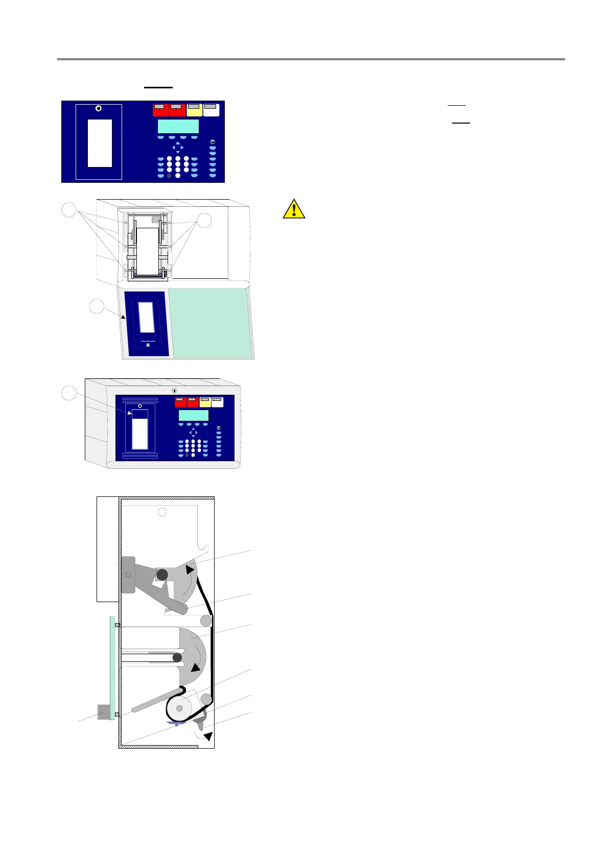
21.2 Printer with paper take-up reel (Part No. 7863xx)
Fig. 118: Panel front (Part No. 7863xx
1
)
Panel front with heat transfer printer with paper take-up reel.
Panel front for heat transfer printer with paper take-up reel
(Part No. 7863xx) and printer kit for IQ8Control C / M (Part No.
784792)
1)
Language identification, e.g. 00=german, 01=English etc.
(refer to catalogue Fire Alarm systems)
1
2
1
3
Fig. 119: Mounting / Replacing
Damage to the system
Remove all power from the panel before carrying out
any installation work (battery and mains power
supply).
Mounting / Replacing
1. Open housing and remove all electrical connections to
the mounted control panel (if existing).
2. Remove the printer by releasing the six screws
.
3. Insert new printer in the mounting frame and fit screws
.
4. Connect printer
(Ribbon cable and
+12 V DC power supply) (ref. next Page Fig. 125)
5. Release paper clamps (
B+F) of the printer and insert
paper roll. Clamp
F must be manually locked again.
6. Release the inserted acrylic plastic sheet
at clampers
and insert the new with the blue pad
, for covering the
paper run.
7. Close housing.
A
B
C
D
E
F
G
A
Paper take-up reel
B Paper clamp, released
C Paper roll
D Rubber drum
E Printing head
F Head clamp, released
G Board with terminals for the power supply connection and
ribbon cable (Centronics)
Fig. 120: Paper roll and paper take-up reel

 Loading...


