Fire Alarm Control Panel IQ8Control C / M
68 FB 798951.10.GB0 / 04.15
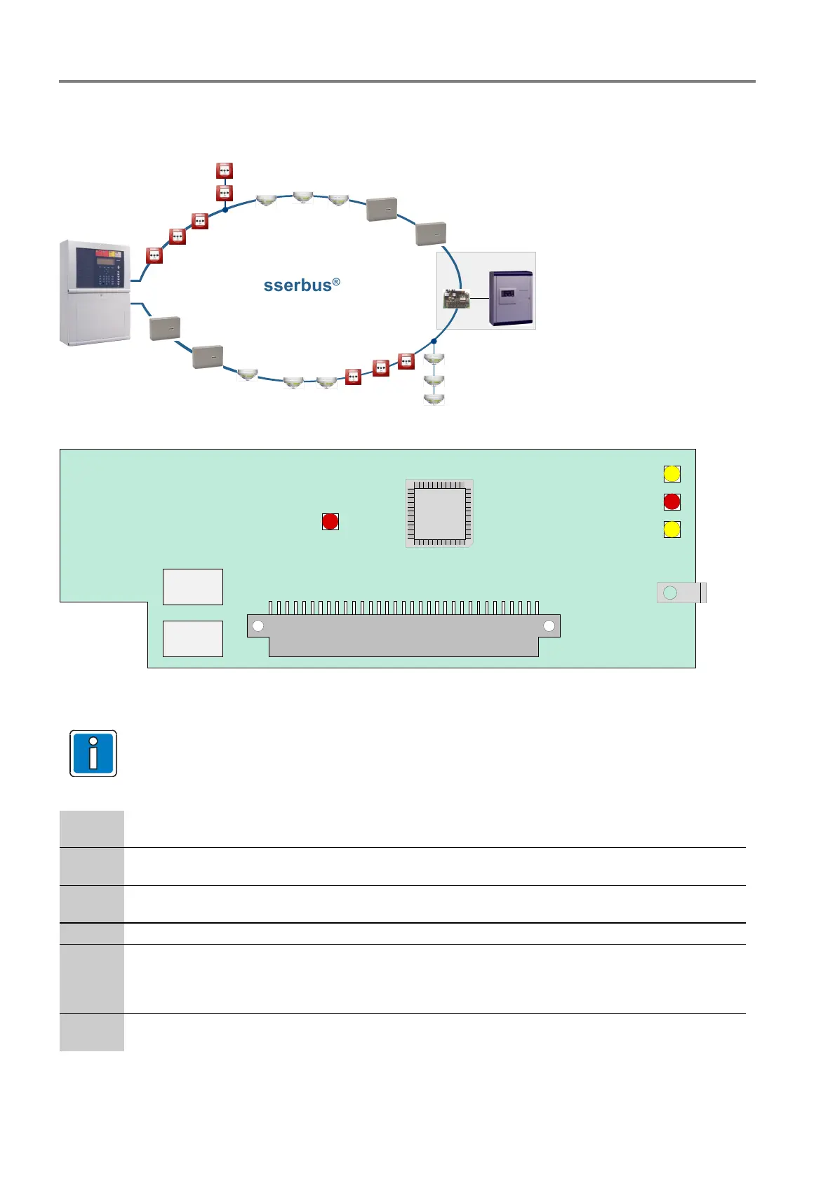
7.1.1 esserbus
®
loop module (Part No. 784382 / 784382.10 / 784382.D0)
The loop module allows for esserbus
®
connection and is configured with Programming software tools 8000
from V1.15.
esserbus
®
Fire alarm and extinguishing
computer 8010
Fig. 57: Exampleesserbus
®
K2 (B)
K1 (A)
LED 2
LED 3
LED 4
LED 1
Loop module
X1
Fig. 58: Loop module (Part No. 784382 / 784382.10 / 784382.D0)
Connect cable shielding of the loop only at one side.
When using the module in door control systems, place the enclosed labels on or in the FACP
housing (see chapter 14.1).
X 1
64-way plug connector to micro module slot of the Basic module, Field device module or
Extension module
K1, K2
Bi-directional loop interrogation by loop isolators
(K1 = A+, A- / K2 = B+, B-)
LED 1
(SMD) red, flashing in normal mode in time with communication on the loop
(SMD) red, lit
Short circuit on loop
LED 2
(SMD) yellow, lit Module faulty
LED 3
(SMD) red, flashing + 24 V power supply failure or communication to
control panel processor interrupted
(SMD) red, lit
Module in CPU failure mode
(control panel CPU failure)
LED 4
(SMD) yellow, flashing Processor program running – normal mode
(SMD) yellow, flashing rapidly
Module in test mode

 Loading...


