Fire Alarm Control Panel IQ8Control C / M
FB 798951.10.GB0 / 04.15 85
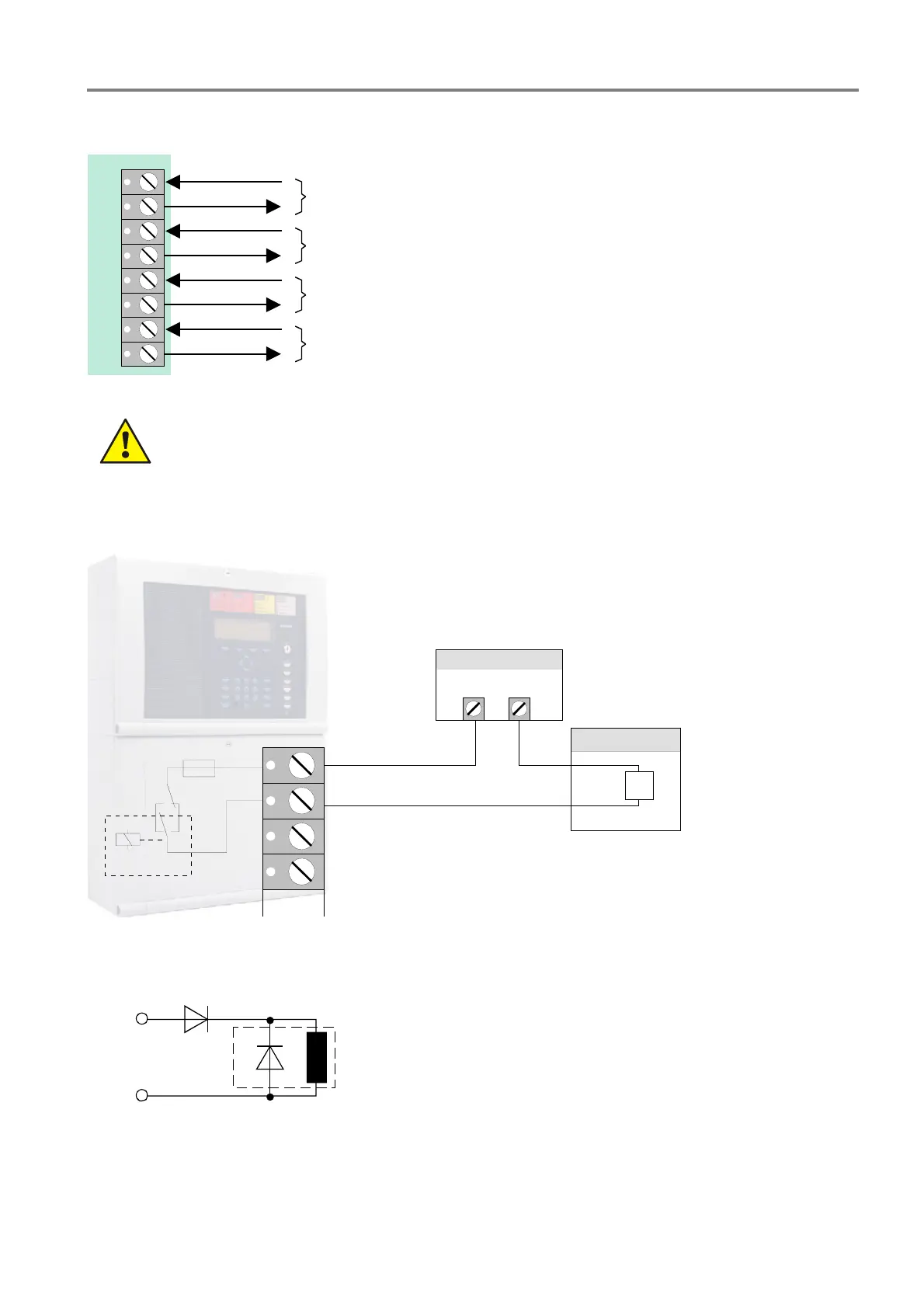
Terminal card assignment
1
2
3
4
5
6
7
8
ext. device at relay K1
ext. device at relay K3
ext. device at relay K4
ext. device at relay K2
Fig. 74: Terminal card assignment
Observe permitted torque (max. 0.4 Nm) of the terminals!
Schematic circuit diagram (example using relay K1)
K1
F1
S1
1
2
Power supply
+-
-
+
3
4
external device
Fig. 75: Schematic wiring external devices
L = inductive load
D
1
= series diode BY251
(notice relays current max. 2 A)
D
2
= recovery diode e.g. 1N4007 o.ä.
L
D
1
D
2
+
-
relay
Fig. 76: Schematic wiring of inductive loads

 Loading...


