Flex 402 & Flex 404 Instruction Manual — P/N 52194:D4 3/27/2015 25
Installation of Optional Modules Installation
on the circuit. Do not wire to the corresponding A+ and A- terminals on the CAC-4 module. Note
that Zone 1 IDC on the Flex 402 and Zone 2 IDC on the Flex 404 can be configured as a
combination waterflow/supervisory circuit as illustrated in the following figure.
2.6.2 4XTMF, 4XLMF and 4XZMF Option Modules
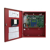
Flex 404: The 4XLMF LED Interface Module can only be plugged into connectors J3 and J5 on
the Flex 404 main circuit board. The 4XTMF and 4XZMF modules can be plugged into
connectors J3 and J5 or
J4 and J6 on the Flex 404 main circuit board. A combination of any two of
the three modules can be installed.
Flex 402: Only the 4XTMF module can be plugged into connectors J3 & J5 on the Flex 402 main
circuit board. (No other option modules can be installed on the Flex 402).
Figure 2.11 Wiring NACs and IDCs for Class A Operation
CAC-4 Class A Converter Module
Flex 404
Circuit Board
Class B (Style B)
IDC - 4.7 KΩ
½ watt ELR
resistor
P/N:71252
(supervised and
power-limited)
Dummy load all unused
circuits - 4.7 KΩ
½ watt ELR resistor
(P/N: 71245)
Polarized
Bell
Circuit polarities
shown in alarm
condition
Class A (Style Z) NAC
(supervised and power-limited)
Class A
(Style D) IDC
(supervised and
power-limited)
Class A
(Style D) IDC
Combo Waterflow &
Supervisory
20KΩ, ½ watt ELR
resistor P/N:75477
(supervised and
power-limited)
1.2 KΩ
½ watt
In-Line
resistor
P/N:75579
Polarized
Strobe
Polarized
Horn
Tamper
Tamper
Waterflow
Smoke
Smoke
Pull
Station
Pull
Station
Heat
Heat
IMPORTANT! All
devices must be
within 20 feet of the
Class A portion of
the circuit and
wiring must be in
conduit.
ms4comba.wmf

 Loading...


