30 Flex 402 & Flex 404 Instruction Manual — P/N 52194:D4 3/27/2015
Section 3: Program Options via DIP Switch
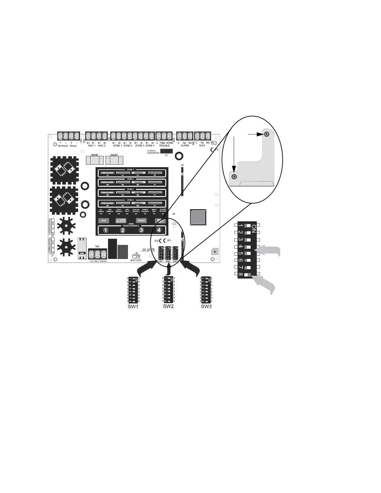
This section describes the programming options available via DIP switch settings. The FACP can
be field programmed using option DIP switches SW1, SW2, and SW3 which are located in the bot-
tom right side of the main circuit board. A factory-installed dip switch cover, which prevents acci-
dental programming, must first be removed. Once programming is complete, the cover must be
reinstalled. Refer to the following illustration for switch locations and DIP switch placement in the
ON and OFF positions.
Figure 3.1 Field Programming DIP Switches
Switches 1 through 7
shown in OFF position
Switch 8 shown in
ON position
ms4switc.wmf
To remove dip switch
cover, remove the two
screws, pull upper arm
(A) partially from hole,
then unhook the
bottom side of cover
(B) from circuit board
edge. Replace when
programming is
complete.
cover2.wmf
screws
(B)
(A)
 Loading...


