Galaxy Dimension Installer Manual
2-2
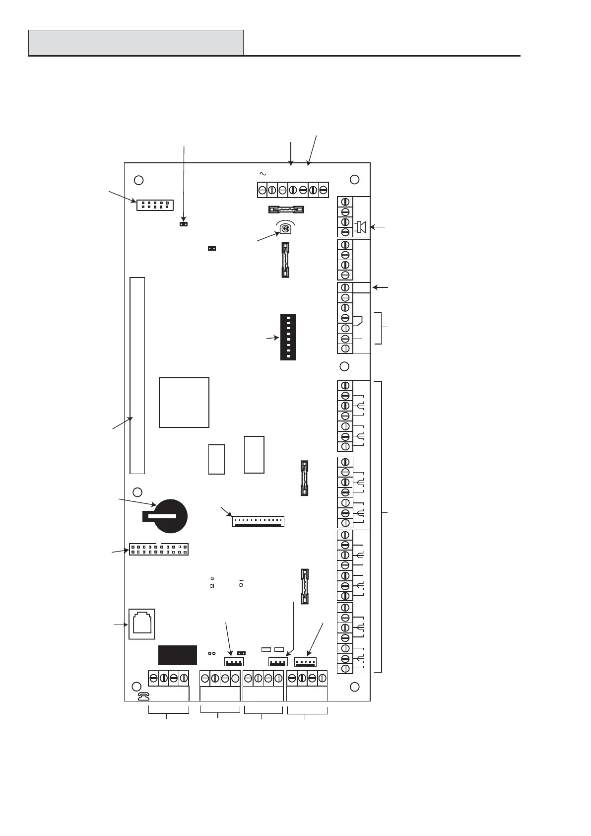
PCB Layout
PCB Layout
Figure 2-2. PCB Layout
LID
TAMP
+12V
+12V
+12V
+12V
1
2
3
4
2
AUX
TAMP
G
N
D
RX
TX
B2
A2
A1
B1
+12V
PHONE
LINE
A
B
AB
AC
MICRO
PROCESSOR
Telecom
Socket
16 on-board zones
External
loudspeaker
Leads for
lid tamper
microswitch
RS232 Port
Jumper Lead
for off-wall
tamper switch
RS485 line 1
RS485 line 2
Telecom
Connect
Battery
terminals
Expansion card
interface
Horn output
volume control
RIO 0
13
RIO 1
GND
GND
+12V
CTS
RTS
LED1(for Telecoms)
LED2 (for RS232)
LK5 RS485 line 1, 680
9
termination
LK3 RS485 line 2, 680
9
termination
+12V
4
14.5
+BAT
-BAT
F1
F2
BATT
AUX3
F4
AUX2
FLASH
RAM1
SPI
Program
Header
OFF WALL
TAMPER
BATTERY
START UP
1
2 3
4 5
6
7 8
SW3
RIO
SWITCH
Engineer socket
(RS485 Line1)
Engineer socket
(RS485 Line 2)
NOTE: Fuse AUX1 controls
RS485 line 1, RIO 0 (zones 1-8)
Fuse AUX2 controls
RS485 line 2, RIO 1 (zones 1-8)
Fuse AUX3 controls an independent
12V output which can be used for a
communicator or screw.
RS232 Port socket
Memory
backup
battery
Pull-up switches
Relay
Output
N/O
C
N/C
ON
NOTE: Zones 1-8 (RIO 0 line 1)
Zones 1-8 (RIO 1 line 1 (switch SW3-8 OFF))
OR
Zones 1-8 (RIO 1 line 0 (switch SW3-8 ON))
1
2
0V
3
4
0V
RIO 0
5
6
0V
7
8
0V
1
2
0V
3
4
0V
RIO 1
5
6
0V
7
8
0V
F3
SKT2
Trigger
Header
LK2
LK4
Debug
Header
AUX1
AUX3
 Loading...


