Mounting and installation
12
Connecting the thermal actuators
Damage to the underoor
heating controller.
Take the technical data into account at
thermal actuators:
Total of 3A maximum current, 250mA
continuous current per zone.
!
Each zone can control up to 3 thermal actuators. 3
thermal actuators can be connected directly for Zone
1, 2 for Zone 2 and 1 thermal actuator each for Zones
3 through 5. One connection for the expansion module
is available for each of the zones 6 through 8.
If more than 11 thermal actuators are to be connected to
the underfloor heating controller, the cables of the thermal
actuators must be connected in a distribution box.
1
If applicable, install the cables of the thermal
actuators to the distribution box.
2
Wire the wires of the thermal actuators.
3
Break out the openings for the cables on
the housing using a diagonal cutter.
14
Strip the connections 5.5 mm (see
fold-out page, Fig. 6).
5
Insert the connecting cables of the thermal actuators
into the cable openings of the connectors.
6
Close the terminals.
7
Plug the connectors into the sockets
of the corresponding zones (see fold-
out page, Fig. 4 (Z1...Z8)).
8
Clamp the cables into the stress relief clamp.
9
Secure the cable with the cable clamp.
Connecting a pump
(
230 V AC
)
As soon as a zone is active, the pump is
activated with a time delay. The pump switches
off as soon as all the valves are closed.
The LED (see fold-out page, Fig. 3 (6)) lights
up green when the pump is running.
The pump contact is not floating. The pump can
be connected directly, see circuit diagram.
Damage to the underoor
heating controller.
Short-circuit at incorrect installation.
Connect all the controllers
to the same phase.
!
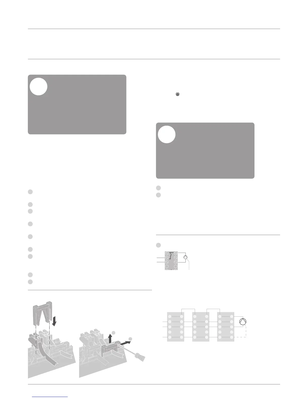
1
Strip the connections 7 mm (see fold-out page, Fig. 7).
2
Connect the pump (see fold-out page, Fig.4 (12)).
Installation Disassembling
1
2
Cabling –
continued
 Loading...