50489/GTEX Chem IIC/1805 UTImeter Gtex Chem IIC
7. Examples of installation of the gauging system
7.1. General
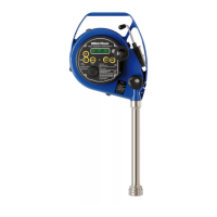
The gauging system consists of the HERMetic
instrument and the associated HERMetic valve.
Two types of connector can be provided as shown
on Figure 8-1.
Figure 8-1
The following sections, respectively 8.2, 8.3 for
connector Q2 and 8.4, 8.5 for connector Q1,
describe 2 examples for installing the valves and
adjusting the height of the gauging system.
The valves should be installed in such a way that
the zero-ullage level coincides with the reading
index level, so that no correction would be
necessary. For achieving this it may be necessary
to install an adjusting pipe between the deck and
the valve.
If the valves are installed directly on deck or if for
any reason the level of the reading index is below
or above the zero-ullage level, then a correction
table should be used.
There should be no internal tank structure
between the valve outlet and the tank bottom such
that will impede the path of the equipment into the
tank.
All valves shall be installed at the same level.
Small systematic level error can be corrected by
adjusting the reading index accordingly.
When designing the gauging port and to avoid
damaging the tape during rewinding it is advised
to chamfer or to grind all sharp edges (on pipes,
flanges, etc.) that could damage the tape when
operating the gauge.

 Loading...


