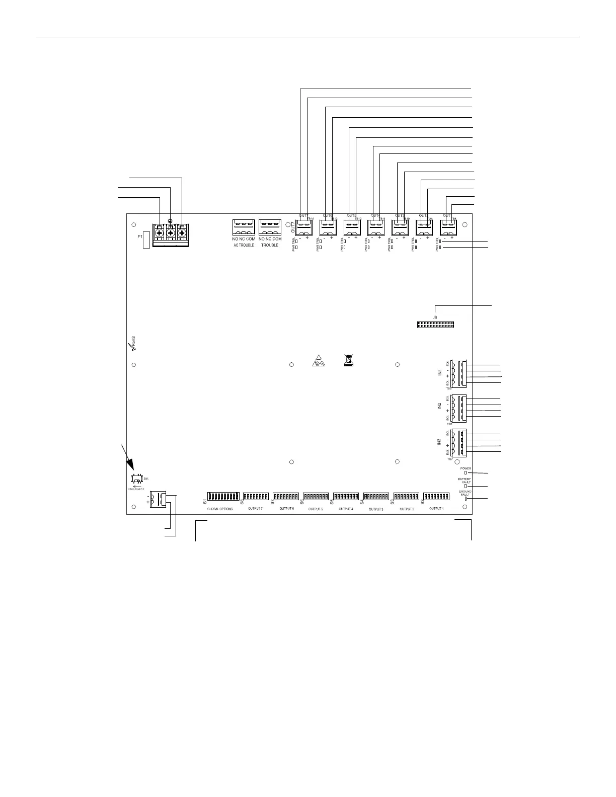
Figure 1.1 HPF-PS10 Board Layout
NAC/Out 7 -
NAC/Out 7 +
NAC/Out 6 -
NAC/Out 6 +
NAC/Out 5 -
NAC/Out 5 +
NAC/Out 4 -
NAC/Out 4 +
NAC/Out 3 -
NAC/Out 3 +
NAC/Out 2 -
NAC/Out 2 +
NAC/Out 1 -
NAC/Out 1 +
TB4 AC Power
Supervised,
Non-power-limited
AC2 (Neutral)
Earth
AC (Hot)
Form-C
Fail-Safe Relays
Non-supervised
(shown energized)
TB5, TB6, TB7
Command Inputs
Input #1
A+
B-
B+
A-
Input #2
A+
B-
B+
A-
Input #3
A+
B-
B+
A-
TB15 Supervised
+ Battery
- Battery
24 VDC
Non-power-limited
S2-S8
Programming DIP Switches
Activate output DIP switch changes by setting S1
positions 9 and 10 appropriately. Refer to page
page 27 for DIP Switch programming settings.
Each output circuit has its own dedicated
programming DIP switch
J8
ZNAC-PS Connector
Power-limited (Class 2), Supervised, Special
Application or Regulated Outputs
LEDs
Power (green)
Batt/Chgr Fault (yellow)
Ground Fault (yellow)
Global
Options
Output 7 Output 6 Output 5 Output 4 Output 3 Output 2 Output 1
S1
Programming DIP Switch
for global options
Output Status LEDs
Trouble (yellow)
Power (red)
Note: The HPF-PS6 uses the same PCB
layout, however some terminals will be
depopulated, leaving the HPF-PS6 with
five output circuits and two inputs circuits.
SW1 Ground Fault
Detection
(slide left to disable)
(slide right to enable)