Appendix B: Application Examples
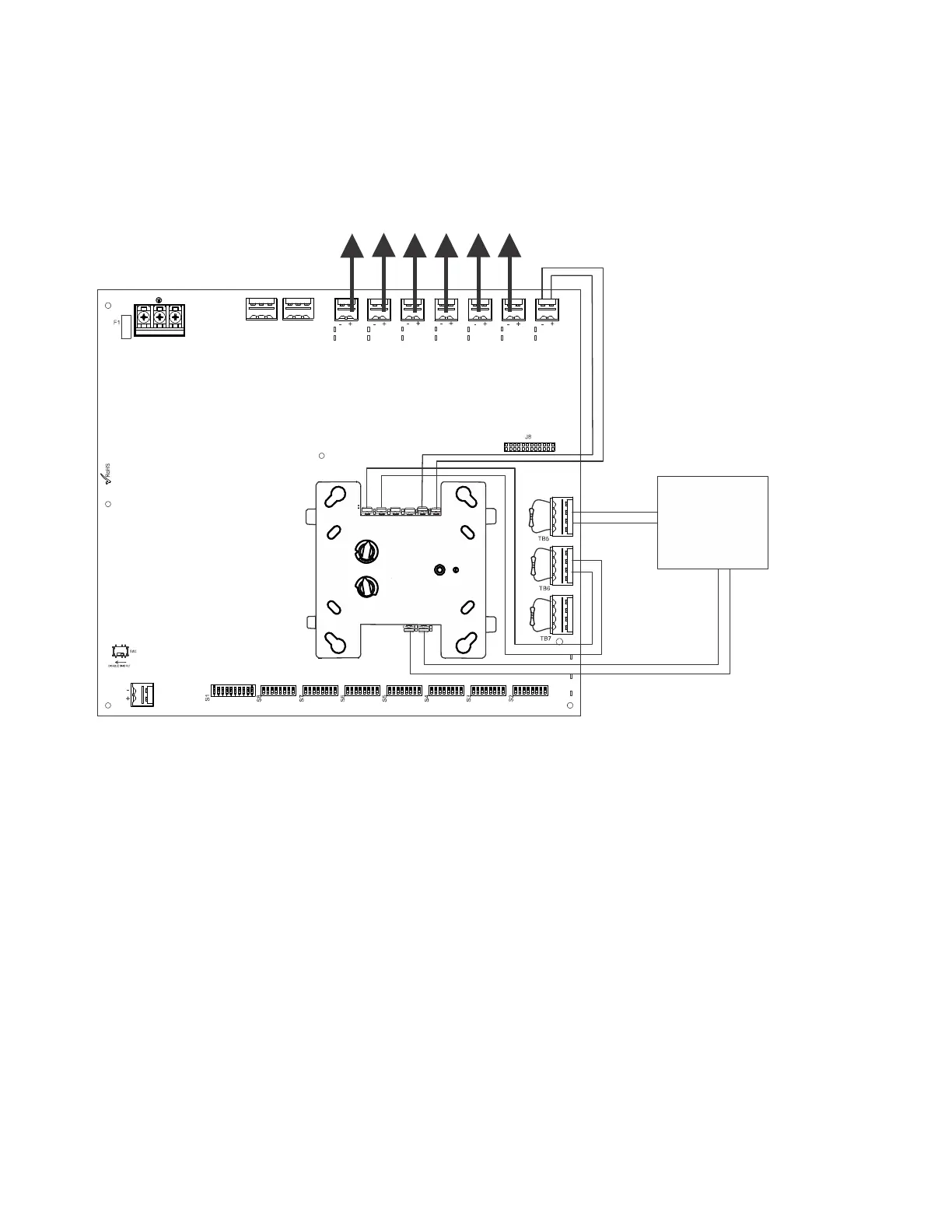
B.1 Controlling NACs For Selective Silence Operation Using a Control Module
In this application, the power supply has been set as a master with synchronized outputs and selective silence (see DIP switch settings and
Selective Silence Operation information in Section 3). This application requires Input #1 to be controlled by the FACP. Input #2 is required
for controlling selective silence via a control/relay module, programmed as an alarm output and a silenceable point. Only Mass Notification,
Fire, or combo Mass Notification/Fire NACs are allowed in this configuration. The control module can be powered by one of the HPF-PS
output circuits, configured as aux power (24VDC).
The following notes apply to Figure B.1.
When the HPF-PS power supply is in an inactive state (FACP NAC not active), a trouble on the NAC circuit will result in an open circuit
condition on the FACP (monitored by End-of-Line Resistor across TB5, Terminals 1 and 4). As an alternative, the trouble contacts at TB1 of
the power supply can also be used for limited trouble monitoring excluding Selective Silence output faults. Refer to Section 5 for more infor-
mation.
• Refer to Section 3 for instructions on setting the DIP switches.
• Selective Silence output faults are only reported via Command Input #1 (not Command Input #2).
• Wire NACs as shown on page 14.
• Do not loop wires under screw terminals. Break wires to maintain proper supervision.
• An End-of-Line Resistor must be installed across all input circuits, Terminals 1 and 4, for control module wiring supervision (the ELR
value is dependent on the module/FACP employed).
• For a list of compatible devices, refer to the HPP Device Compatibility Document #54399.
• Refer to the SLC Wiring Manual for more information.
NO NC CNONC C
TB4
TB15
T
B
2
T
B
1
T
B
1
3
T
B
1
2
T
B
1
1
T
B
1
0
T
B
9
T
B
8
T1
T11
T2
T10
T3
T9
T4
T8
T5
T7
T6
A- B+ B- A+ A- B+
Figure B.1 Controlling Multiple Outputs with One Input
Control Module*
SLC
*If the SLC device does not match
the one in this figure, refer to the
SLC manual wiring conversion
charts for legacy and newer ver-
sions of the modules.
NAC Output Circuits
24VDC power output
NAC
FACP
HPF-PS Series Instruction Manual — P/N LS10227-003HP-E:C 2/2/2022
43