GB-3
Type label
▷
Gas type, measurement time, installation po-
sition, mains voltage, mains frequency, power
consumption, ambient temperature, enclosure,
max. switch-on current and max. inlet pressure–
see type label.
TC
D-49018 Osnabrück, Germany
t
M
(s) 5 10 15 20 25 30
Installation
CAUTION
Please observe the following to ensure that the unit
is not damaged during installation and operation:
– Dropping the device can cause permanent dam-
age. In this event, replace the entire device and
associated modules before use.
– Avoid formation of condensation in the device.
– Do not store or install the unit in the open air.
– Check max. inlet pressure.
– Use a suitable spanner. Do not use the device
as a lever. Risk of external leakage.
▷ Installation in the vertical or horizontal position,
housing cover/indicators must not point upwards
or downwards. The electrical connection should
preferably be pointing downwards or towards
the outlet.
▷
The device must not be in contact with masonry.
Minimum clearance 20mm (0.78").
▷ Use the O-rings supplied.
▷
In the case of very large test volumes V
P
, an
installed relief line should be of nominal size40
to allow for the discharge of the test volumeV
P
.
Disconnect the system from the electrical power
supply.
Shut off the gas supply.
43
5
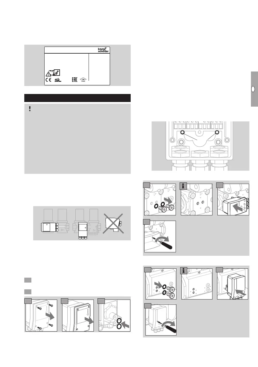
▷ The O-rings must be inserted in the connectors
of theTC.
Mounting TCV to valVario controls
▷ The solenoid actuator cannot be rotated on so-
lenoid valves with proof of closure switch VCx..S
or VCx..G.
▷
Connect the TC to the inlet pressure connec-
tionp
u
and the interspace pressure connection
p
z
of the inlet valve. Ensure that connections p
u
and p
z
on the TC and the gas solenoid valve
are not reversed.
▷ TC and bypass/pilot gas valve cannot be fitted
together on the same side of the double block
valve.
▷
When using a valve/pressure regulator combi-
nation VCG/VCV/VCH, the pressure regulator
must be activated with air during the entire test
periodt
P
.
▷
The TC is secured using two captive combination
Torx screws T20(M4) inside the housing. Do not
undo any other screws!
Torx T20
VAS – , VCx –
max. 250 Ncm
6 7
8
p
u
p
z
VAS 6 – 9, VCS 6 – 9
p
u
p
z
6
7
8
max. 250 Ncm
 Loading...


