GB-7
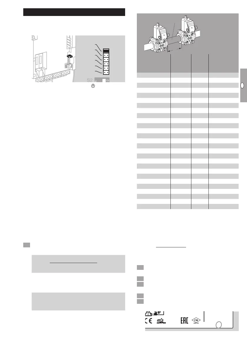
Setting measurement time t
M
▷
The measurement time t
M
can be set with a
jumper in increments of 5s to max. 30s.
▷ t
M
is set to 30s at the factory.
M
5s
10s
15s
20s
25s
30s
▷
No jumper: no function. The
LED is perma-
nently red, see page 8 (Assistance in the
event of malfunction).
▷
The longer the measurement timet
M
, the greater
the sensitivity of the tightness control. The longer
the measurement time, the smaller the leakage
rate at which a safety shut-down/fault lock-out
is triggered.
▷
For all CG versions, the measurement
timet
M
must be set to 5s on TC1C.
▷ If no leakage rate is specified, we recommend
the max. measurement time is set.
▷
Within the scope of the European Union, the
maximum leakage rate Q
L
is 0.1% of the maxi-
mum flow rate Q
max.
[m
3
/h (n)].
▷ If a leakage rate is specified, find the measure-
ment timet
M
from the following:
Q
max.
= max. flow rate [m
3
/h]
Q
L
= Q
max.
[m
3
/h] x 0.1% = leakage rate [ l/h]
p
u
= inlet pressure [mbar]
V
P
= test volume [ l ], see page7 (Values for
valve and pipe volume)
▷
The tightness control TC requires a minimum
start rate in order to carry out tightness tests
on slow opening valves:
up to 5l (1.3gal) test volume V
P
= 5% of maxi-
mum flow rateQ
max.
, up to 12l (3.12gal) test
volume V
P
= 10% of maximum flow rateQ
max.
.
Determine measurement time t
M
.
▷ Measurement times t
M
for V1 and V2:
t
M
[s] =
2.5 x p
u
[mbar] x V
P
[ l ]
Q
L
[ l /h]
▷
The entire test period is made up of the meas-
urement timest
M
of both valves and the fixed
opening timet
L
of both valves together:
t
P
[s] = 2 x t
L
+ 2 x t
M
Values for valve and pipe volume
L
V
P
= V
V
+ L x V
V
P
V1
V2
Valves
Valve
volume
V
V
[ l ]
Nomi-
nal size
DN
Pipe
volume V
R
[ l/m]
VG 10 0.01 10 0.1
VG 15 0.07 15 0.2
VG 20 0.12 20 0.3
VG 25 0.2 25 0.5
VG 40/VK 40 0.7 40 1.3
VG 50/VK 50 1.2 50 2
VG 65/VK 65 2 65 3.3
VG 80/VK 80 4 80 5
VG 100/VK 100 8.3 100 7.9
VK 125 13.6 125 12.3
VK 150 20 150 17.7
VK 200 42 200 31.4
VK 250 66 250 49
VAS 1 0.08
VAS 2 0.32
VAS 3 0.68
VAS 6 1.37
VAS 7 2.04
VAS 8 3.34
VAS 9 5.41
VCS 1 0.05
VCS 2 0.18
VCS 3 0.39
VCS 6 1.11
VCS 7 1.40
VCS 8 2.82
VCS 9 4.34
Calculation example:
Q
max.
= 100 m
3
/h
p
u
= 100 mbar
V
P
= V
V
+ L x V
R
= 7 l
Q
L
= 100 m
3
/h x 0.1% = 100 l/h
2.5 x 100 x 7
= 17.5 s
100
Set the next highest value (in this example 20s)
with the jumper.
Disconnect the unit from the electrical power
supply.
Unscrew the housing cover.
4 Set the jumper to the position for the required
measurement time.
5 Position the housing cover and screw tight.
6 Mark the set measurement timet
M
on the type
label with a waterproof pen.
TC
D-49018 Osnabrück, Germany
t
M
(s) 5 10 15 20 25 30
▷ The entire test period for this example is as fol-
lows: 2 x 3 s + 2 x 20 s = 46 s.
 Loading...


