GB-8
7 Switch on the power supply.
▷
The
LED flashes yellow (0.2 s on/off). After
10s, the TC accepts the new setting and
is
yellow or green, see table on page 8 (Com-
missioning).
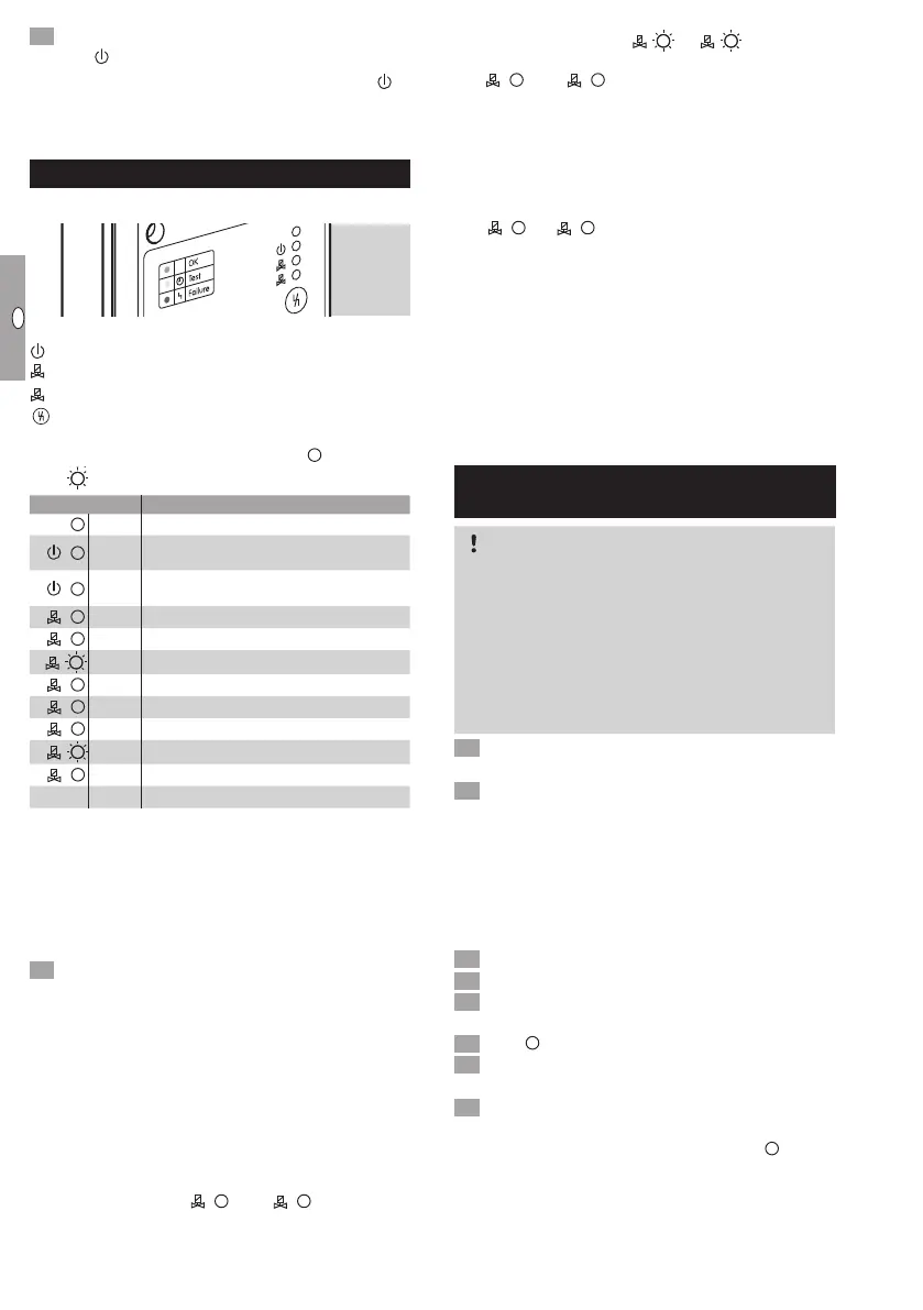
Commissioning
Indicators and operating controls
1
2
Power
= power supply
= operating signal
= valve 1
= valve 2
= reset button
The LEDs can display messages using three colours
(green, yellow, red) and permanent
or flashing
light
:
LED Messages/Operating status
green Power supply OK
yellow
TC is ready for operation; no safety
interlock* input signal
green
TC is ready for operation; active
safety interlock* input signal
green V1 is tight
yellow V1 is untested
1
yellow Tightness test is running on V1
red V1 is leaking
green V2 is tight
yellow V2 is untested
2
yellow Tightness test is running on V2
red V2 is leaking
All yellow Initialization
* Linking of all the relevant safety control and switching
equipment for the use of the application. The burner
start enable signal is issued via the safety interlock
output (terminal 6).
▷
For further messages, see page 8 (Assis-
tance in the event of malfunction).
Switch on the mains voltage.
▷
All LEDs are yellow for 1s. The TC is in the
initialization phase.
▷
The test starts according to the test instant
(Mode) which has been set.
Mode 1 or Mode 3, test before burner start-up:
voltage is applied to terminal 10 (thermostat/
start-up signalϑ).
Or
Mode 2, test after burner run: the TC shows the
last operating status. In the case of untested
valves, the LEDs
and
are yellow.
There is mains voltage at terminal1 and renewed
test after switching off the voltage to terminal10
(thermostat/start-up signalϑ).
▷ During the test, the
1
or
2
LED flashes
yellow.
The
and
LEDs are green:
▷ Both valves are tight.
Mode 1 or Mode 3: the enable signal is issued via
terminal6 when voltage is applied to terminal5.
Or
Mode 2: the enable signal is issued via terminal6
when voltage is applied to terminals 10 and5.
The
or
LED is red:
▷ A valve is leaking.
▷ Voltage at terminal 12. A fault signal is output.
Power failure
▷ If the power fails briefly during the test or during
operation, the tightness test will restart in accord-
ance with the test procedure described above.
▷ If there is a fault message, the fault is displayed
again after a power failure.
Assistance in the event of
malfunction
CAUTION
Electric shocks can be fatal!
– Before working on possible live components,
ensure the unit is disconnected from the power
supply.
– Fault-clearance must only be undertaken by
authorized trained personnel!
– (Remote) resets may only be conducted by au-
thorized trained personnel.
• Faults may be cleared only using the measures
described below.
• Press the reset button to test whether the TC
restarts.
▷
If the tightness control will not start even though
all faults have been remedied, remove the entire
TC (in the case of TC 3, including auxiliary valves
and corresponding valve block) and send it to
the manufacturer for inspection.
? Fault
! Cause
• Remedy
?
red and permanently lit?
! There is over-/undervoltage. The TC performs a
safety shut-down.
• Check the mains voltage. As soon as there is
no longer over-/undervoltage, the TC returns to
normal operating mode and the
LED is
green. It is not necessary to reset the device.
 Loading...


