Do you have a question about the Honeywell MS-10UD Series and is the answer not in the manual?
| Category | Smoke Alarm |
|---|---|
| Type | Photoelectric |
| Power Source | 120VAC |
| Alarm Sound Level | 85 dB at 10 feet |
| Hush Feature | Yes |
| LED Indicator | Yes |
| Battery Backup | 9V |
| Operating Temperature | 40°F (4.4°C) to 100°F (37.8°C) |
| Compliance | UL 217 |
Details key features of the MS-5UD and MS-10UD series FACP.
Outlines technical specifications including AC power, battery, and circuit details.
Describes panel control buttons, LCD display, and LED indicators for system status.
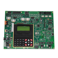
Lists the main components of the FACP, including circuit boards, power supply, cabinet, and batteries.
Details optional modules and accessories like converters, annunciators, and printer interfaces.
Covers telephone line requirements, DACT usage, and important warnings for installation.
Provides instructions for mounting the FACP backbox and chassis securely.
Explains AC and battery power connections, including safety precautions.
Describes the Initiating Device Circuits (IDCs), their configuration, and compatibility.
Details Notification Appliance Circuits (NACs) and DC power output configurations.
Specifies requirements for separating power-limited and nonpower-limited wiring within the cabinet.
Explains the connection and wiring of the FACP's digital communicator.
Guides the installation of optional modules like converters, annunciators, and printer interfaces.
Covers ANN-BUS wiring, distance calculations, and device addressing for accessories.
Introduces user programming methods, passwords, and levels for FACP configuration.
Details access to programming screens for system setup, input zones, NACs, and relays.
Explains how to program and configure input zones, including type, verification, and descriptions.
Covers programming NAC circuits for enabled status, coding, silence, and auto-silence features.
Describes how to program the function of the FACP's Form-C relays.
Covers system configuration options like timers, banner, time-date, and trouble reminders.
Details configuration options for ANN-BUS modules and the onboard DACT.
Explains the function of panel control buttons like Acknowledge, Silence, Drill, and Reset.
Describes the meaning of each LED indicator on the FACP front panel.
Details the system status display and background operations in normal mode.
Explains how the FACP indicates and manages trouble conditions.
Describes FACP behavior during an alarm condition, including notifications and relay activation.
Details FACP behavior for supervisory events like tamper or freeze conditions.
Covers special timers for silence inhibit, auto-silence, trouble reminders, and waterflow.
Explains the procedure for performing system walktests and viewing results.
Describes how to view system status, programming, history, and configuration details.
Lists the priority order for transmitting events to central stations.
Details the process and requirements for remote programming and interrogation of the FACP.
Explains procedures and security features for uploading and downloading FACP programs.
Introduces the process for calculating power supply currents and battery requirements.
Guides on determining the required AC branch circuit current for system operation.
Explains how to calculate system current draws for standby and alarm conditions.
Details the method for calculating battery size based on standby and alarm loads.
Describes the transmission string format for Ademco Contact ID.
Provides examples of typical alarm and trouble reports in Ademco Contact ID format.
Lists minimum components required for NFPA 72 Central Station Service compliance.
Outlines additional equipment needed for NFPA 72 Auxiliary Fire Alarm System compliance.
Details requirements for NFPA 72 Proprietary Fire Alarm System applications.
Explains connecting FACP dry contacts to central station transmitters.
Illustrates connections between the FACP and Keltron Receiver/Transmitter modules.
Provides NAC wiring requirements for FLPS-3 power supply models.
Provides NAC wiring requirements for FLPS-7 power supply models.
States the warranty period, obligations, and exclusions for Honeywell products.
