PAGE - 20 Manuale di installazione AM-8000
NOTIFIER ITALIA Doc. 160.1-AM8000-ITA Rev A.3 AM8000_manu-inst
System Network Wiring
EN54
!
EN54-2
8.2.6 - 12.5.3
Panels with
components in
separate cabinet:
Fault condition &
indication.
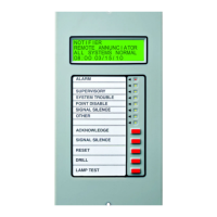
Both LCD-8000-F and LCD-8000-L units are integral part of the AM-
8000 system. This implies that are “not only” events repeaters, but
also enable the operator to perform all EN 54.2 mandatory
functions like configuration, test, disabling etc.
What said, implies that the connection to the AM-8000 CAN-Bus
MUST BE wired in Class A ( Loop ) configuration.
And also the Power supply connection MUST BE in the same
configuration.
If this function is not appropriately followed, it can contravene the EN54
requirements.
Here are some samples of the power supply and CAN bus wiring.
Note that :
Each LCD have TWO connections for the CAN Network
Each LCD have TWO connections for the Power Supply
CAN-Bus IN-OUT connections must be wired in separated path
LCD Power IN-OUT connections must be wired in separated
path
Power source for the LCD-8000L and LCD-8000F can be :
One Black Box for all LCDs , or….
Each LCD can be powered from the nearest Black Box , or….
One LCD can use a local EN 54.4 certified Power Supply unit but
in this case the Power line must be splitted and the two
connection path must be physically separated.
 Loading...
