FCPS-24S Series Instruction Manual — P/N 51977:J2 7/11/2014 17
Addressable Module Mounting Installation
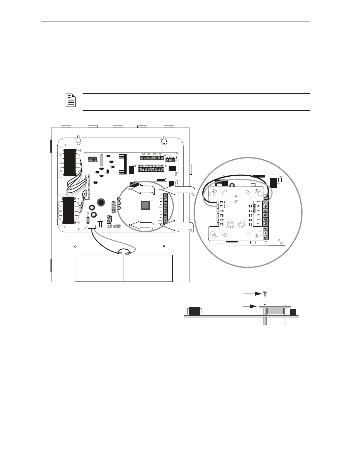
2.3 Addressable Module Mounting
The FCPS-24S has been designed to allow the mounting of an addressable control, relay or monitor
module on the main circuit board inside the power supply cabinet with the module status LED visi-
ble through the closed door. This allows power to be fed from the FCPS-24S Auxiliary Power out-
put directly to the module, if needed, without running the power wires outside the cabinet. As an
example, Figure 2.5 illustrates wiring from the Auxiliary power output terminals to a FCM-1 con-
trol module’s terminals 3 (-) and 4 (+).
2.4 NEC Power-limited (Class 2) Wiring Requirements
Power-limited (Class 2) and nonpower-limited circuit wiring must remain separated in the cabinet.
All power-limited (Class 2) circuit wiring must remain at least 0.25” away from any nonpower-lim-
ited circuit wiring. Furthermore, all power-limited (Class 2) circuit wiring and nonpower-limited
circuit wiring must enter and exit the cabinet through different conduits. One such example of this
is shown below. Your specific application may require different conduit knockouts to be used. Any
conduit knockouts may be used. For power-limited (Class 2) applications, use of conduit is
optional.
NOTE: The module mounting kit (P/N 90286) is pre-installed on the power supply main circuit
board.
standoff
standoff
standoff
standoff
24fsmodltpH.wmf
*If the SLC device does not match the one in this figure,
refer to the SLC manual wiring conversion charts for leg-
acy and newer versions of the modules.
Module Installation
1. Place addressable module over (4) standoffs and
secure with (4) supplied screws.
2. Wire module as shown in illustration above.
Figure 2.5 Mounting Module In FCPS-24S Cabinet
addressable module
mounting screw
24smodinstl.wmf
 Loading...