ID2000 Series Installation & Commissioning Manual
Installation - Panel Electronics
26997-433-000-5, Issue 5
May 2010
5.5 Extension Chassis
The ID2000 Series extension chassis is required for
zones 17-80 LEDs and/or for mounting the ID2000 Series
PRN-ID printer. The extension chassis is very simple to
fit providing the instructions below are followed.
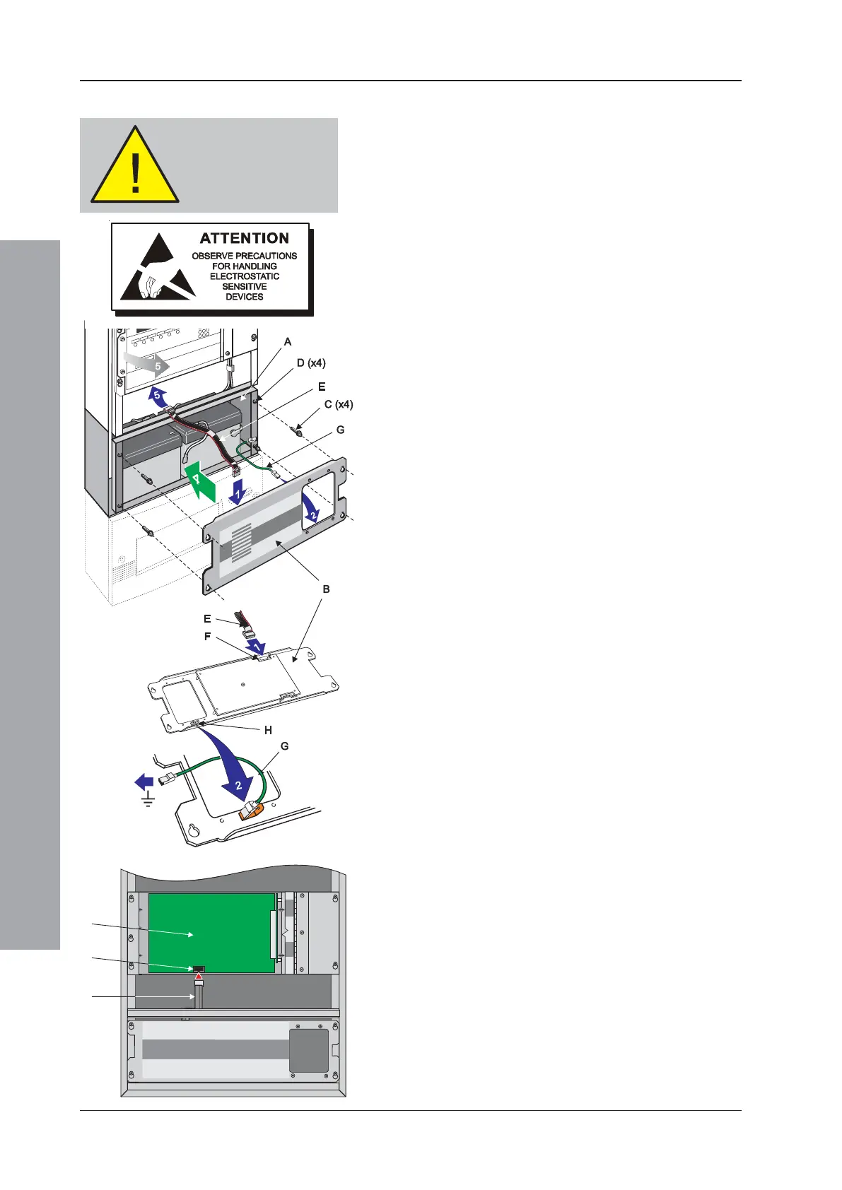
Taking suitable anti-static precautions, such as wearing
a grounded wrist strap, remove all packaging and inspect
for any damage that may have occurred in transit. If no
damage is evident, proceed with these instructions.
Before attempting this procedure, make sure ALL
power to the control panel is disconnected.
5.5.1 Zones 17-80 LED Extension Chassis
With the back box (A) secured to the wall in its chosen
location and with the batteries installed, fit the extension
chassis (B) as follows:
1 Locate the four supplied M4 x 16 SEM screws (C) in
the back box holes (D) and insert them approximately
half way.
2 Connect one end of the supplied, 10-way ribbon cable
(E) to the top connector (F), marked ‘IN’, of the LED
PCB.
3 Connect one end of the supplied earth lead (G) to
the earthing blade terminal (H) on the extension
chassis.
4 With the extension chassis correctly orientated (refer
to drawing at left), locate the keyholes onto the four
screws with the threaded part in contact with the top
flats of the keyholes.
5 With the extension chassis now located on the back
box, open the main chassis front door and connect
the other end of the 10-way ribbon cable at socket
SK19 (I) on the Base PCB (J).
6 Connect the other end of the earth lead to the earthing
blade terminals located inside the back box and to the
right of the chassis.
Note: All blade connections to earth incorporate a
locking barb. To remove this connection, press
the release tab on the connector.
7 Having made the connections described in steps 5
and 6 above, use a Posidriv No.2 screwdriver to
secure the extension chassis.
Note: When the panel is ready for the connection of
power, use the aperture on the right-hand side of
the extension chassis to access the wiring to make
the last connection to the batteries - refer to
Section 8.5.1, Connecting the Batteries.
5.5.2 Extension Chassis (with Printer)
Refer to Section 5.6.
CAUTION!
Make sure ALL power to
the panel has been
disconnected.
 Loading...


