ID2000 Series Installation & Commissioning Manual
Commissioning
43
997-433-000-5, Issue 5
May 2010
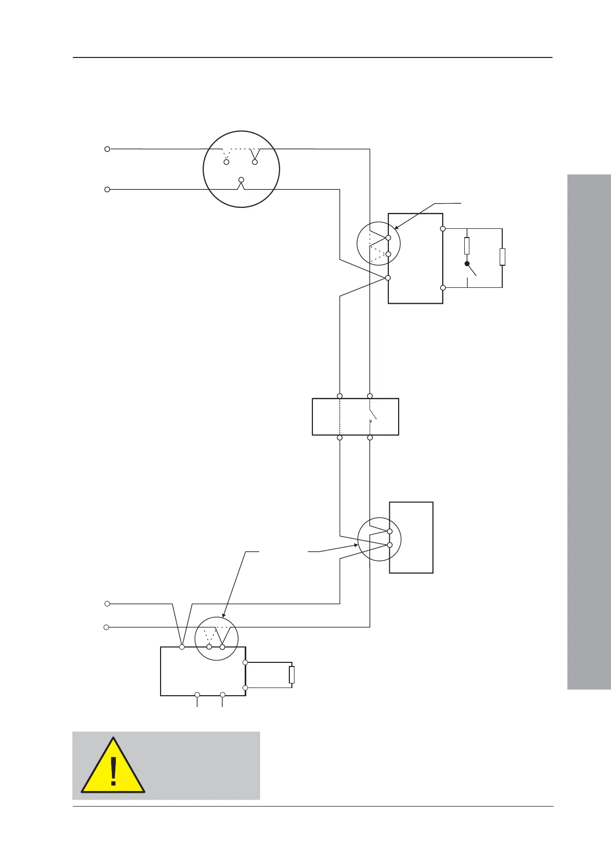
8.4.2 Loop Checks Before Connecting Wiring
Typical connections of analogue addressable devices
to a loop are shown below.
Loop
Start
B501/B501 AP (see Note 3)
B501/B501 AP (see Note 3)
Monitor used
as input
Loop
Finish
Output Module
Supervised
Load
28V Supply
Isolator (see Note 2)
M500KAC/
M700KAC
See Note 1
See Note 3
1. A = Normally open switch - closes under an
alarm condition.
2. To comply with the requirements of EN54-2,
isolators should be fitted between a maximum
of 32 loop devices. For the ID2000 Series, do
not place more than 25 loop devices between
isolators (20 if FET isolators are used).
3. Refer to device instruction sheet for wiring
terminations.
1. A = Normally open switch - closes under an
alarm
condition.
2. To
comply with the requirements of EN54-2,
isolators
should be fitted between a maximum
of
32 loop devices. For the ID2000 Series, do
not
place more than 25 loop devices between
isolators
(20 if FET isolators are used).
3. Refer
to device instruction sheet for wiring
terminations.
See Note 3
See Note 3
LOOP IN
LOOP IN
LOOP IN
LOOP OUT
LOOP OUT
LOOP OUT
The loop wiring MUST
be disconnected from
the panel during this
procedure
For checking the loop wiring, do the following:
1 For CLIP devices link out any isolators on the Loop
by temporarily shorting terminals 2 and 4 on each
isolator. For OPAL protocol-compatible sensor bases
(B501 AP) remove the device from the base. These
bases have +leg terminals (+2 and +4) that connect
automatically when the sensor is removed. Check
 Loading...


