ID2000 Series Installation & Commissioning Manual
Appendix 2
A2 - 2997-433-000-5, Issue 5
May 2010
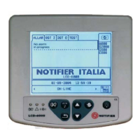
Displays and Indications:
Alphanumeric display: 2-line x 40-character back-lit LCD
LED Status Indicators: DISABLEMENT, TEST, EARTH
FAULT, POWER SUPPLY FAULT,
SYSTEM FAULT, POWER, PRE-
ALARM, SOUNDERS DISABLED,
SOUNDER FAULT, DELAY ACTIVE,
DAY MODE.
Zone Indicators: Individual FIRE and Fault indicators
for 16 or 80 zones (depending upon
configuration options).
Controls:
Dedicated flush push-buttons are provided for the following functions:
MUTE BUZZER
ACCEPT
EVACUATE
SILENCE SOUNDERS
RESOUND SOUNDERS
RESET
Additional pushbuttons for programming and selection of software
functions:
10-KEY NUMERIC KEY-PAD
KEYS
AND KEYS
KEY
System Capacity:
Number of loops: Up to 8 depending upon
configuration options.
Number of zones: 16 or 80 depending upon
configuration options.
Devices per loop: 99 sensors + 99 modules or
99 sensors + combination of up to
99 modules/sounders within strict
limits.
External Connections:
Cable entry: 25 x 20mm knock-outs in top of
cabinet, 15 in rear, 4 in bottom.
Terminals: All external connections made
through screw terminals, each of
which will accept cable sizes
between 0.5 mm
2
and 2.5 mm
2
.
Electrical:
Classification: Installation Class I, (panel must be
earthed)
Supply Rating:
Mains supply to the panel is to be provided via an external double-
pole mains isolation unit. The supply rating is:
230V~(ac) ± 15%, 5A, 50Hz ± 4%
Fuse Rating (of terminal block):
T 5A 250V H Ceramic
 Loading...


