NFS-320 and NFS-320SYS UL Listing Document — P/N 52745LD:G9 5/19/2022 11
UL Power-limited Wiring Requirements
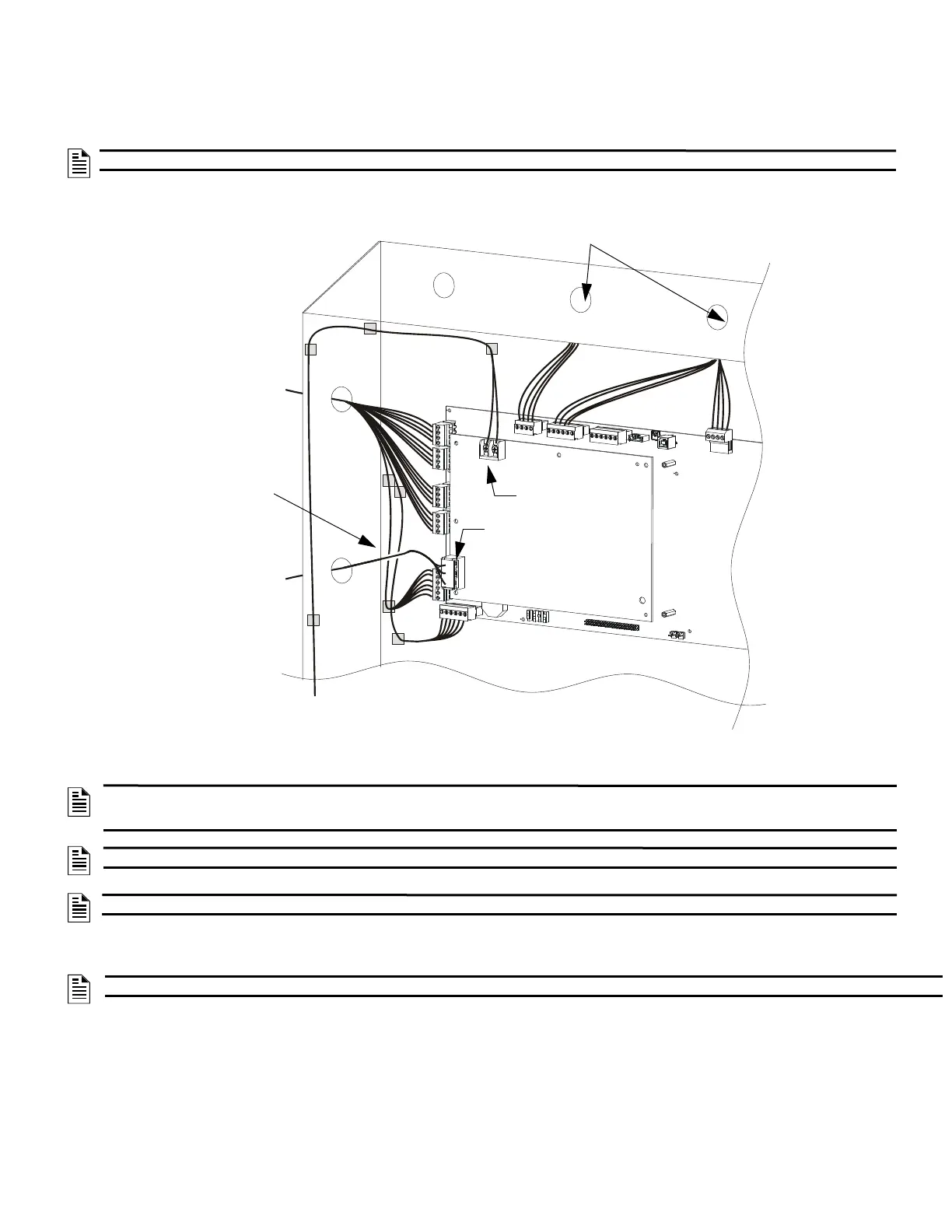
Power-limited (Class 2) and non-power-limited circuit wiring must remain separated in the cabinet. All power-limited circuit wiring must remain at
least 0.25 inches (6.35 mm) from any non-power-limited circuit wiring. All power-limited and non-power-limited circuit wiring must enter and exit the
cabinet through different knockout and or conduits. To maintain separation, group non-power limited modules together, i.e., group modules on the
same side of the enclosure or in separate rows.
Figure 16 shows one configuration that meets these UL requirements. Equipment is configured with at least a 0.25 inch (6.35 mm) separation between
power-limited and non-power-limited wiring. AC and battery wiring is routed away from power-limited wiring.
1.3 Fire/Security Applications
General Operation
The NFS-320 can be used as a combination Fire/Security system when installed and operated according to the instructions in this section.
For security applications, program one or more monitor module (listed for security applications) with the security-L, system monitor, or area monitor
Type Codes, and wire as shown in Figure 17. Activating these types of modules lights the security LED, and displays a security alarm condition on the
primary display. The panel sounder will sound until you acknowledge the Security alarm. You can also program additional sounders or output devices
to activate with the security alarm initiating device. These type codes are designed to indicate an alarm in one or more of the following situations:
NOTE: If additional knockouts are added to the backbox, proper separation of power-limited and non-power-limited wiring should be maintained.
NOTE: AC and battery wiring are not power-limited. Maintain at least 0.25 inches (6.35 mm) between power-limited and non power-limited
circuit wiring. Install tie wraps and adhesive squares to secure the wiring. Use a power-limited source for relay output on terminals TB8 – TB11.
See Figure 13, "CPU Wiring Connections" to identify power-limited and non-power-limited circuits.
NOTE: Drawing is not to scale; proportions and angles are exaggerated to show wire-placement more clearly.
NOTE: The NFS-320 is not approved for use in security applications in Canada.
NOTE: The NFS-320 is not approved for use in security applications in Canada.
320-2-640-PWRLMTWIR-ISO2.wmf
Figure 16 Typical Wiring for UL Power-limited Wiring Requirements
(Shown with relays as connected to power-limited modules)
Power-limited Circuits
NPL (Non-power-
limited
circuits)
To cabinet-mounted battery
(non-power-limited)
Power-limited
circuits
NPL
NPL
Maintain vertical
separation where
circuits appear to
“cross”

 Loading...


