NFS-320 and NFS-320SYS UL Listing Document — P/N 52745LD:G9 5/19/2022 15
Security Annunciation
A1P1
Mode: Monitor
Source: ZLc
A1P2
Mode: Monitor
Source: ZLe
A1P3
Mode: Monitor
Source: LXXMYY
A1P4
Mode: Monitor
Source: LXXMYY
Additional doors can be monitored, up to the number of available annunci-
ator points.
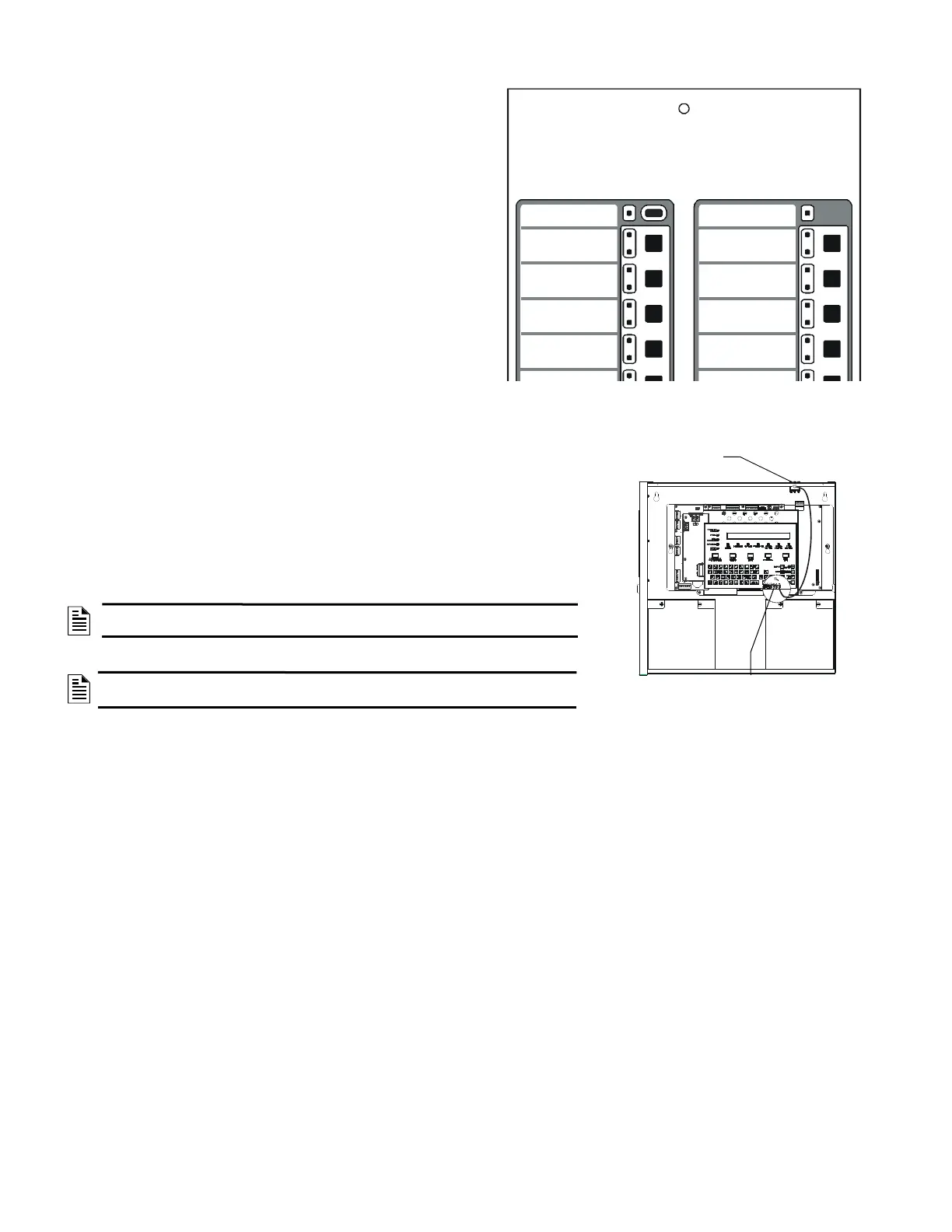
To wire the cabinet with a Security Tamper Switch kit model STS-200 or
STS-1:
Refer to Figure 20:
1. Install the STS-200 or STS-1 Tamper Switch into the location shown in 20. Push the
switch through the opening until it snaps into place.
2. Connect the STS-200 or STS-1 connector to J5 (Security Tamper) on the Control Panel.
(As shown in figure 20, J5 is located on the circuit board, underneath the edge of KDM-
R2/C.)
NOTE: When installing a Security Tamper Switch, use the STS-200 for the NFS-320.
For the NFS-320SYS, use the STS-1.
NOTE: Total SLC points connected to the FACP are limited to 1000 or less for
burglar-alarm applications
Figure 19 Sample Annunciator Display
System Status
(red is armed)
System Alarm
(red is alarm)
Entry/Exit Door 1 Status
(red is unsecured)
Entry/Exit Door 2 Status
(red is unsecured)
Connect to
J5 “Security Tamper”
STS-200 mounting
location
Figure 20 Installing the STS-200 Security
Tamper Switch

 Loading...


