16 NFS-320 and NFS-320SYS UL Listing Document — P/N 52745LD:G9 5/19/2022
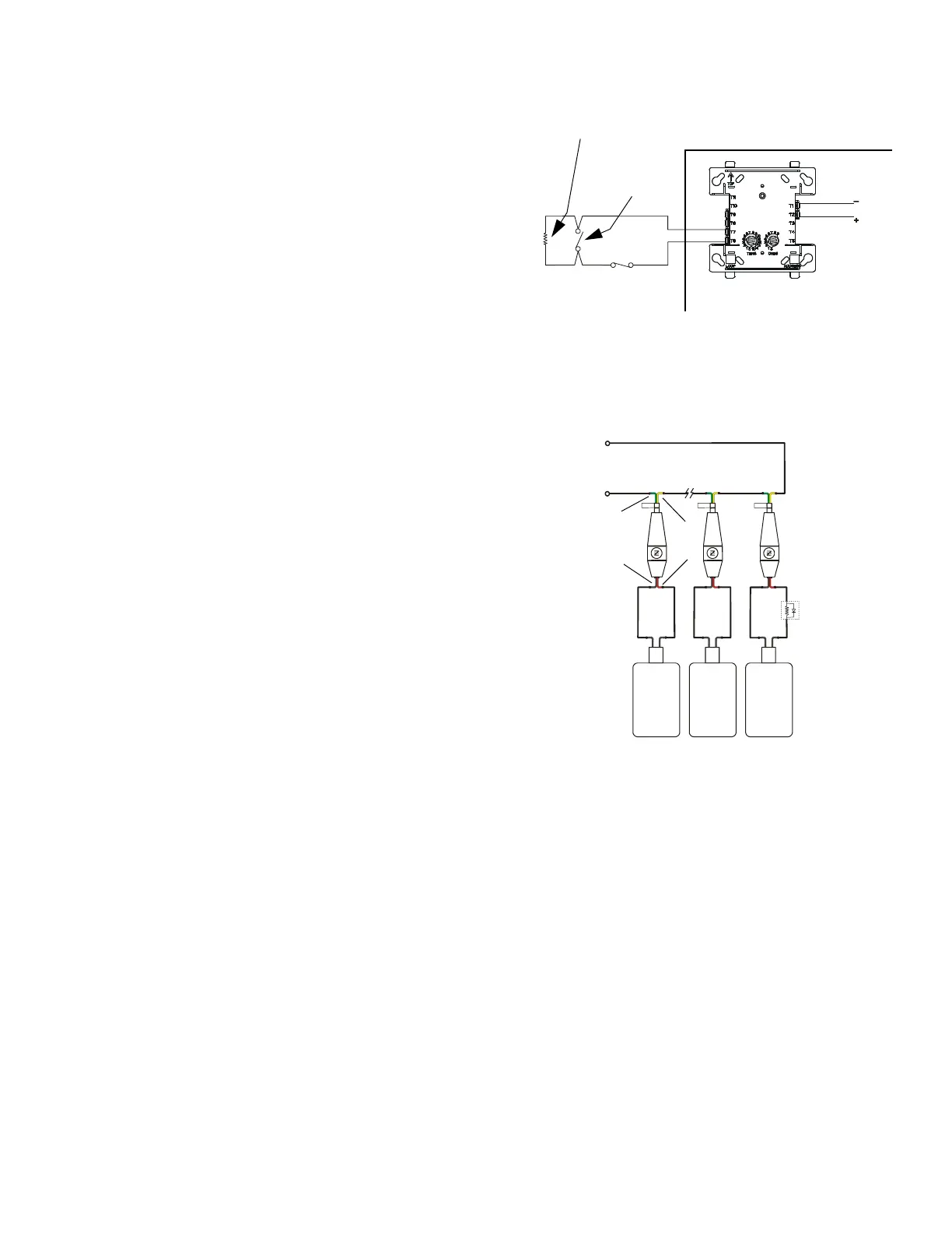
Typical wiring for proprietary security alarm applications with monitor modules
Figure 21 shows typical wiring for proprietary security alarm applications with
FMM-1 modules. Note the following:
• The module is programmed with software SECURITY Type Code.
• For use with UL listed systems only; application not for ULC security usage.
• NAC devices used for security cannot be shared with fire NAC devices.
• Refer to the Device Compatibility Document for compatible NAC devices.
• All monitor modules used for security application must be installed in the
NFS-320 cabinet with STS-1 Security Tamper Switch or NFS-320SYS cabinet
with STS-1 Security Tamper Switch.
Typical wiring for STAT-X devices using the Ematch Protection Device (P/N 3005014)
Refer to Figure 22 and note the following:
• Each Stat-X device requires an Ematch Protection Device to protect against
high-voltage transient signals, such as lightning, that may cause the device to
accidentally release.
• Multiple Stat-X devices can be connected in series (as shown).
• No more than ten (10) Stat-X devices can be connected on a single releasing
circuit.
• A REL-2.2K can be installed on a single Stat-X device for short circuit
detection. For multiple Stat-X devices installed in series, the REL-2.2K is
installed on the last device on the releasing circuit (as shown). A REL-2.2K is
required for ULC applications.
• Stat-X devices are not to be used with the FCM-1 or FCM-1-REL.
FlashScan Monitor Module
UL-listed, normally-closed
security switch
UL-listed,
normally-open
security switch
SLC
Channel
A or B
NFS-320 Protected
Premises Unit
CPU2-640-burgtpH.wmf
UL-listed 47K
End-of-Line Resistor
(provided with module)
Figure 21 Wiring Diagram for Proprietary Security
Alarm Applications
Stat-X
Stat-X
Stat-X
REL-2.2K
Releasing Circuit
+
_
Ematch Protection
Device
P/N 3005014
Figure 22 Wiring Diagram for Stat-X Devices
Yellow
Green
Red
Black
StatXMultiEOL.wmf

 Loading...


