NFS-320 and NFS-320SYS UL Listing Document — P/N 52745LD:G9 5/19/2022 39
8 System Power/Size
9 Operating Instructions
Frame and mount the NFS-320 Operating Instructions, p/n 52748, adjacent to the control panel. See back of this manual.
KEY:
Y - Yes N - No O - Optional
NOTES:
1. The system must contain either one of the two displays.
2. The system must contain at least one of the units.
3. Also required when devices for Carbon Monoxide signaling are employed.
4. Each NFS-320SYS/NFS-320SYSE must include at least one enclosure.
5. This equipment for use with the NFS-320SYS/NFS-320SYSE only.
6. Various dress panels/dead fronts/ trim rings must be employed so that internal components and high voltage is not accessible
7. Required if utilizing a central station other than supported by CGW-MB
The units may employ the following features:
• Alarm verification (maximum verification period of 60 for field programmable between 0 and 60s)
• Supports standard 2-wire smoke detectors using Models FZM-1. refer to the Device Compatibility Document for compatible 2-wire smoke detectors
• Supports addressable or analog devices
• Field Programming
• Signal Silence Inhibit
• Remote annunciator outputs
• Automatic Alarm Signal Silence
• Drift compensation
• Detector sensitivity testing per Par. 7-3.2.1 of NFPA 72
8. Required when using CGW-MB alone OR using a CGW-MB with CGW-PT OR using CGW-DACT.
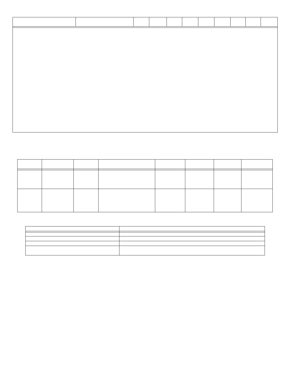
Power Current
Max. AH
Capacity
Derating Factor
Max. Standby
Current
Max. Alarm
Current
Max. Standby
Time
Max. Alarm
Duration
Primary
(Power Supply)
5A (CPS-24 Power
Supply)
or
2.5A (CPS-24E
Power Supply)
N/A N/A 891 mA (CPS-24)
or
498 mA (CPS-24E)
2.4 A (CPS-24)
or
1.46 A (CPS-24E)
N/A N/A
Secondary
(backup)
7.4A 200AH 26 AH batteries: UL=1.2, ULC=1.5
55 AH batteries: UL=1.2, ULC=1.8
100 AH batteries: UL=1.2, ULC=2.5
200 AH batteries: UL=1.2, ULC=2.5
4.4A
(For 26AH
batteries: max
standby current
cannot exceed
0.65A)
7.4A
(max alarm
current cannot
exceed 6.75A)
24 hours 5 minutes standard,
15 minutes for
emergency voice/
alarm
communications
systems.
Table 13 System Power
Accessories/Subassemblies/Networked panels Maximum System Capacity
Monitor and Control Modules 159
Detectors 159
Initiating Device Circuits (SLC) 1
NFS-320/NFS-320SYS Fire Alarm Control Panel High-Speed Noti•Fire•Net - 200 Nodes
Noti•Fire•Net - 103 Nodes. 54 nodes when DVC is used in network paging.
Table 14 System Size
Module Description CS Local AUX RS P (PPU) P(Burg) REL P Rec
Process
Mana.
Table 12 System Configuration (3 of 3)

 Loading...


