12 NFS-320 and NFS-320SYS UL Listing Document — P/N 52745LD:G9 5/19/2022
(a) on an open or short circuit
(b) on a ±50% change in resistance value from the End-of-Line resistor value
(c) on loss of communication with the device.
A tamper switch installed in the cabinet door will indicate a door tamper condition whenever the door is open. If the control panel indicates a Security
alarm, you can perform acknowledge, signal silence, and system reset from the control panel.
General Security Requirements
The following security requirements must be met:
• Shielded cable must be used on all input/output wiring associated with security functions.
• SLC Loop Shielding (refer to the SLC Wiring Manual)
• Security Module I/O Circuit Shielding - terminate the shield at earth ground at the junction box containing the module.
• When employed as a Protected Premises Unit, the control panels cabinet door must be wired with an STS-1 Tamper Switch that is monitored by
the control panel
• If the system has arming and disarming capability, a ring-back signal from the Central Station to the arming location is required. The ring-back
signal informs the Protected Premises Control Panel that the signal to arm/disarm has been received by the Central Station
• An ACM-24AT point must be programmed as ‘disable’ for each security point or zone programmed, doing so allows for a manual bypass before
arming if the point or zone is in trouble
• A duplicate control panel or sufficient spare parts should be made available so that the control panel can be brought back online within 30 minutes
of any failure
• There must be a sufficient number of ACM-24AT’s installed on the control panel to show the status of each zone or point so that each zone or
point can be monitored Any ACM-24AT’s or optional annunciators must be installed inside the protected area
• A single control panel combines a Protected Premises Unit and Receiving Unit as a single unit, as such, it must be located in an area that is
monitored at all times
• The Installer should be familiar with and follow the best practices set forth within ANSI/SIA CP-01 for troubleshooting and reduction in dispatch
calls
• The loss of communication with the monitoring station shall be treated as an alarm condition by monitoring station personnel when the burglar
alarm system is in the armed state, and as a trouble condition while the system is disarmed
• Refer to the SLC Wiring Manual (51253) for additional information on required wiring sizes
There are five software type IDs associated with security operation: ACCESS
MONITOR alarm, AREA MONITOR, EQUIP MONITOR, SECURITY-L, and SYS
MONITOR. There is also one software function, Security Delay (SDEL). These
software elements are essential to all aspects of security operation, including
Control-By-Event (CBE) programming. Devices with the type IDs A
CCESS
MONITOR and EQUIP MONITOR do not automatically display at the LCD or
require state change acknowledgment. State changes in devices with these
software types may be output at a printer.Proprietary Security Alarm
Applications
For security applications, program one or more monitor modules (listed for
security applications) with a security type code.
Note the following:
•The module is programed as an ACCESS MONIITOR, AREA MONITOR,
EQUIP MONITOR, SECURITY-L, or SYS MONITOR type code.
• Supplementary use applies to UL Systems only.
• NAC devices used for security cannot be shared with fire NAC devices.
• Refer to the Device Compatibility Document, document number 15378, for compatible NAC devices.
• All monitor modules used for security applications must be installed in the control panel with an STS-1 Security Tamper Switch.
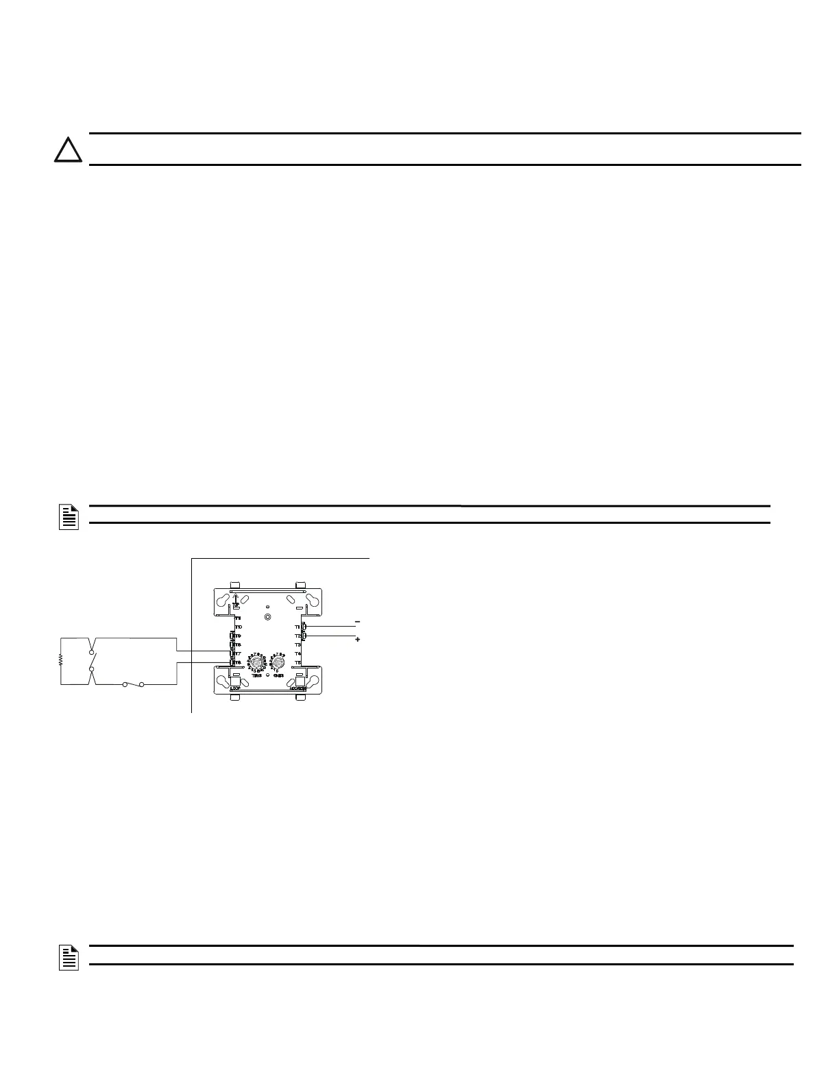
Wiring for Proprietary Security Alarm Applications
Typical wiring for proprietary security alarm applications with the FMM-1 module.
Note the following:
• The module is programmed with one of five type codes (see “General Security Requirements” on page 12).
• Supplementary use only applies to UL-listed systems.
• NAC devices used for security cannot be shared with fire NAC devices.
• Refer to the Device Compatibility Document for compatible NAC devices.
All monitor modules used for security application must be installed in the control panel cabinet with STS-1 Security Tamper Switch.
CAUTION: WIRING
DAMAGE CAN RESULT FROM INCORRECT WIRING CONNECTIONS.
NOTE: For Security applications the maximum number of points on a system must be limited to 1000 or less.
NOTE: If NAC devices are used, the audible pattern for a Security Alarm signal should be distinct from a Fire Alarm
47K
End-of-line
UL-listed,
normally-open
NFS2-3030 Protected Premises Unit
UL-listed,
normally-closed
FMM-1
SLC
Channel A
or B
Figure 17 Wiring Diagram for Proprietary Security Alarm

 Loading...


