NFS-320 and NFS-320SYS UL Listing Document — P/N 52745LD:G9 5/19/2022 3
1.1 NFS-320SYS Option Boards
NOTE: When designing the cabinet layout, consider separation of power-limited (Class 2) and non-power-limited wiring as discussed in Section
“UL Power-limited Wiring Requirements”.
CHS2-M2iso.wmf
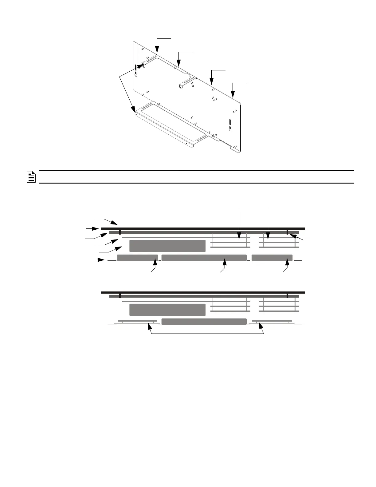
Also see Figure 2, “Top View of
NFS-320SYS Chassis Mounting
Options”
Slot 1 (CPU, CPS-24, and
primary display)
Keypad/display
unit attaches to
chassis rails
Figure 1 Side View of the NFS-320SYS Chassis Mounting Options
Slot 2 (CPU, CPS-24,
and primary display)
Slot 3 (Mounting location
for LEM-320) or other
option board
Slot 4 Mounting location for
option boards and other
compatible peripherals
(Recommended mounting
location for fiber versions of the
NCM and HS-NCM)
CPU
CPS-24/E
DP-DISP2
(or ADP2-640
if in lower row)
Primary Display
KDM-R2/C or NCA-2/C
(mounts to chassis)
Right Annunciator
(mounts to dress panel)
Up to two option boards Up to three option boards
(2 only if longer standoffs
are used)
Option boards
Mounted on BMP-1
CHS2-M2Top.wmf
Backbox
Chassis
Keyhole
Keyhole
Left Annunciator
(mounts to dress panel)
Figure 2 Top View of NFS-320SYS Chassis Mounting Options

 Loading...


