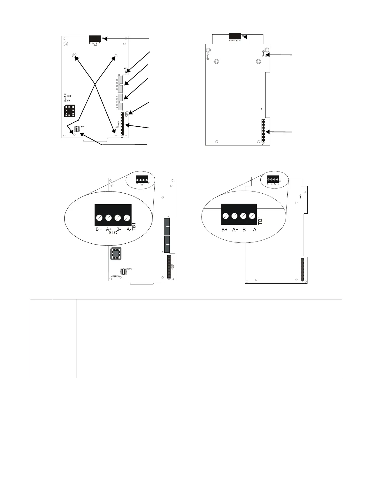
LEM-320LCM-320
TB1
SLC Loop
Connection
JP2
See Note*
J3 Data Out to
next LCM-320
J1
Data In from
control panel or from
previous LCM-320
Ground Fault LEDs:
D32
Loop Expander
Module Ground Fault
D28
Loop Control
Module Ground Fault
J2
LEM-320
Connection
SW1
Set to assign
SLC loop number
TB1 SLC Loop
Connection
JP1 See Note*
J1 LCM-320
Connection
Standoff
locations
*NOTE: Do not cut any jumpers on the LCM-320 or LEM-320.
LCM-320 LEM-320
TB1 SLC
Loop
• Voltage: 24 VDC nominal voltage, 27.6 VDC maximum voltage
• Maximum Current: 400 mA max, 200 mA average (short circuit will shut down the circuit until the short is fixed)
• Wiring Configuration: (Class A, X or B)
• Maximum Length: 12,500 ft (3810 m) total loop length (NFPA Class A, X, and B)
• Maximum Resistance: 50 ohms (Class A, X, or B)
• Device Capacity (per loop):
If loop set as FlashScan: 01- 159 Intelligent Detectors, 01 -159 Monitor/Control Modules
If loop set as CLIP: 01-99 Intelligent Detectors, 01-99 Monitor/Control Modules
• Maximum Capacitance: 0.5 microfarads for all SLC wiring
• Ground Fault Impedance: 0 ohms
• Supervised
• Power-limited (Class 2)
• Connect up to five Loop Control Boards. Additional five loops available with the addition of the Loop Expander Module.
Figure 3 LCM-320 and LEM-320 Board Layout and Connections

 Loading...


