NFS2-3030 Listing Document — P/N LS10006-051NF-E:F2 5/19/2022 7
1.2.3 Option Board Mounting Procedures
Steps to mount option boards are as follows. Mounting instructions for option boards are the same in various dress panels. For Door mounting options,
refer to Figure 7, “Door Mounting Option Boards with a Single-space Blank Plate” on page 8.
1. Install four 1 inch (25.4 mm) stand-offs on the chassis.
2. Install three 1/4 inch stand-offs on the chassis for NCD mounting ONLY
3. Place the first option board over the stand-offs so they line up.
4. If no other option boards will be mounted in that position: Securely fasten board to all stand-offs using screws provided with the module.
If mounting a second or third option board: Attach another layer of stand-offs and repeat steps 2 and 3. Be sure to set the switches on the
option boards before mounting another layer over the previous one. Refer to Figure 5 for layout options.
5. For the top layer of option boards, slide the tab at the bottom of the board into the slots on the chassis and lay the board back onto the top of the
chassis so that the studs line up with the mounting holes on the option board. Securely fasten all stand-offs with screws provided with the module.
1.2.4 CA-2 Chassis
• Occupies two rows of the cabinet.
• Includes hardware to mount an audio command center.
– Backplate to attach to the backbox
– Two half-chassis, which take up the left half of the backbox row
– A microphone and telephone handset well
– A microphone
• CPU occupies the top left half of the chassis
• LCM-320/LEM-320 mounts behind the CPU (See below)
• DVC occupies the bottom left half of the chassis. Refer to the DVC Manual
#52411 for setup options.
Microphone and optional TELH-1 telephone handset can be mounted in the micro-
phone and handset well.
NOTE: For NCD mounting use the CPU 2-3030 NO DISPLAY mounting slot on the CHS-M3 with 1/4 inch standoffs.
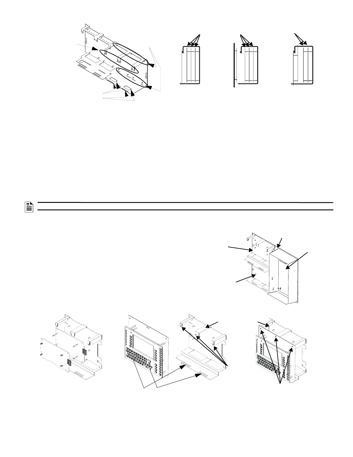
To mount option boards
against the CHS-M3
backplate, attach stand-offs
to the chassis studs
When applicable, slide tabs at bottom
of option boards into the matching slot
To mount option boards in
the front of the chassis, use
standoffs built into the
chassis arms
Layers 1, 2 and 3 mounted to
PEM studs on chassis
Layers 1 and 2 mounted to
PEM studs on chassis
Layer 4 mounted to
PEM studs and tab slot
Layer 4 door mounted Layers 4 mounted to PEM
studs and tab slot; Layer 3
suspended from Layer 4
Layout Options for Mounting Other EquipmentMounting Option Boards in the CHS-M3
Figure 5 Chassis CHS-M3 Equipment Mounting Options
Microphone and
handset well
Half-chassis for
control panel
(FACP) and
optional pair of
Loop Control and
Expander Modules
Half-chassis for DVC
and optional NCM/
HS-NCM
CPU Mounting and Chassis Positions
Backplate
Mounting the CPU2-3030(CPU2-3030DCfor Canada Only) onto the CA-2 Chassis
Mounting the First Set of
LCM-320/LEM-320 in the CA-2
Upper half-chassis
Install three
#4-40 x 1.5”
M/F
standoffs on
the CA-2
Fasten with
four screws
CPU2-3030(CPU2-
3030DCfor Canad Only)
Slide the tabs at the bottom of the control panel
into the inner slot at the bottom of the chassis
Figure 6 Chassis CA-2 Equipment Mounting Options

 Loading...


