14 NFS2-640 UL Listing Document — P/N 52741LD:H9 5/19/2022
Security Annunciation
A1P1
Mode: Monitor
Source: ZLc
A1P2
Mode: Monitor
Source: ZLe
A1P3
Mode: Monitor
Source: LXXMYY
A1P4
Mode: Monitor
Source: LXXMYY
Additional doors can be monitored, up to the number of available annunci-
ator points.
To wire the cabinet with a Security Tamper Switch kit model STS-1:
Refer to Figure 2.
1. Install the STS-1 Tamper Switch onto the side of the backbox opposite the
door hinge, pushing the switch through the opening until it snaps into place.
2. Install the magnet on the same side of the cabinet door as the lock. Push the
magnet through the opening in the door until it snaps into place.
3. Connect the STS-1 connector to J5 (Security Tamper) on the Control Panel.
(As shown in Figure 2, J5 is located on the circuit board, underneath the edge
of KDM-R2.)
For security applications, program one or more monitor modules (listed for secu-
rity applications) with the
SECURITY Type Code, and wire as shown in Figure 3.
Typical wiring for proprietary security alarm applications with FMM-1 modules
See Figure 3, and refer to the following:
• The module is programmed with SECURITY Type Code.
• For use with UL listed systems only; application not for ULC security usage.
• NAC devices used for security cannot be shared with fire NAC devices.
• Refer to the Device Compatibility Document for compatible NAC devices.
• All monitor modules used for security application must be installed in the
NFS2-640 cabinet with STS-200 Security Tamper Switch.
NOTE: Total SLC points connected to the FACP are limited to
1000 or less for burglar-alarm applications
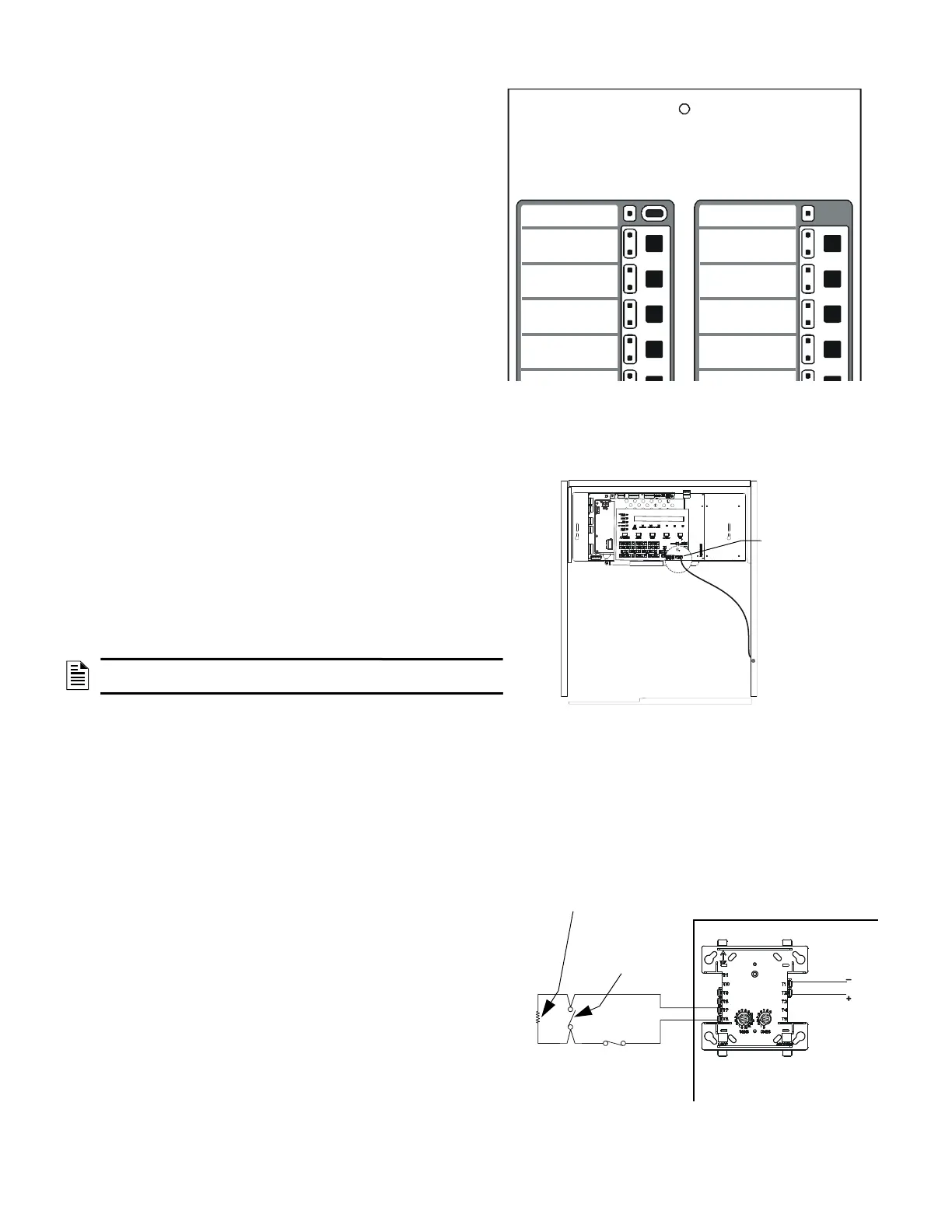
Figure 1.1 Sample Annunciator Display
System Status
(red is armed)
System Alarm
(red is alarm)
Entry/Exit Door 1 Status
(red is unsecured)
Entry/Exit Door 2 Status
(red is unsecured)
CPU2-640-sts1_CPS.wmf
STS-1 mounting
location
(side opposite of
door hinges)
Connect to
J5 “Security Tamper”
Figure 2 Installing the STS-1 Security Tamper Switch
FlashScan Monitor Module
UL-listed, normally-closed
security switch
UL-listed,
normally-open
security switch
SLC
NFS2-640/E Protected
CPU2-640-burgtpH.wmf
UL-listed 47K
End-of-Line Resistor
(provided with module)
Figure 3 Wiring Diagram for Proprietary Security

 Loading...


