40 NFS2-640 UL Listing Document — P/N 52741LD:H9 5/19/2022
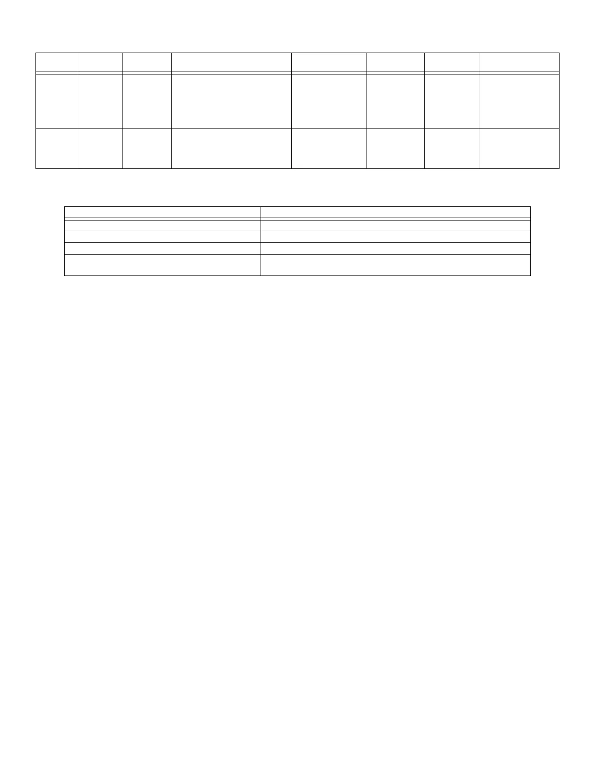
8 System Power/Size
9 Operating Instructions
Frame and mount the NFS2-640 Operating Instructions, P/N 52744, adjacent to the control panel. See the back of this manual.
Power Current
Max. AH
Capacity
Derating Factor
Max. Standby
Current
Max. Alarm
Current
Max. Standby
Time
Max. Alarm Duration
Primary
(Power
Supply)
5A (CPS-24
Power
Supply);
or
2.5A (CPS-
24E Power
Supply)
N/A N/A 891 mA (CPS-24)
or
498 mA (CPS-24E)
2.4 A (CPS-24)
or
1.46 A (CPS-24E)
N/A N/A
Secondary
(backup)
7.4A 200AH 26 AH batteries: UL=1.2, ULC=1.5
55 AH batteries: UL=1.2, ULC=1.8
100 AH batteries: UL=1.2, ULC=2.5
200 AH batteries: UL=1.2, ULC=2.5
4.4A
(For 26AH batteries:
max standby current
cannot exceed 0.65A)
7.4A
(max alarm
current cannot
exceed 6.75A.)
24 hours 5 minutes standard,
15 minutes for
emergency voice/alarm
communications
systems.
Table 13 System Power
Accessories/Subassemblies/Networked panels Maximum System Capacity
Monitor and Control Modules 318
Detectors 318
Signaling Line Circuits (SLC) 2
NFS2-640 Fire Alarm Control Panel High-Speed Noti•Fire•Net - 200 Nodes
Noti•Fire•Net - 103 Nodes. 54 nodes when DVC is used in network paging.
Table 14 System Size

 Loading...


