22 NFS2-640 UL Listing Document — P/N 52741LD:H9 5/19/2022
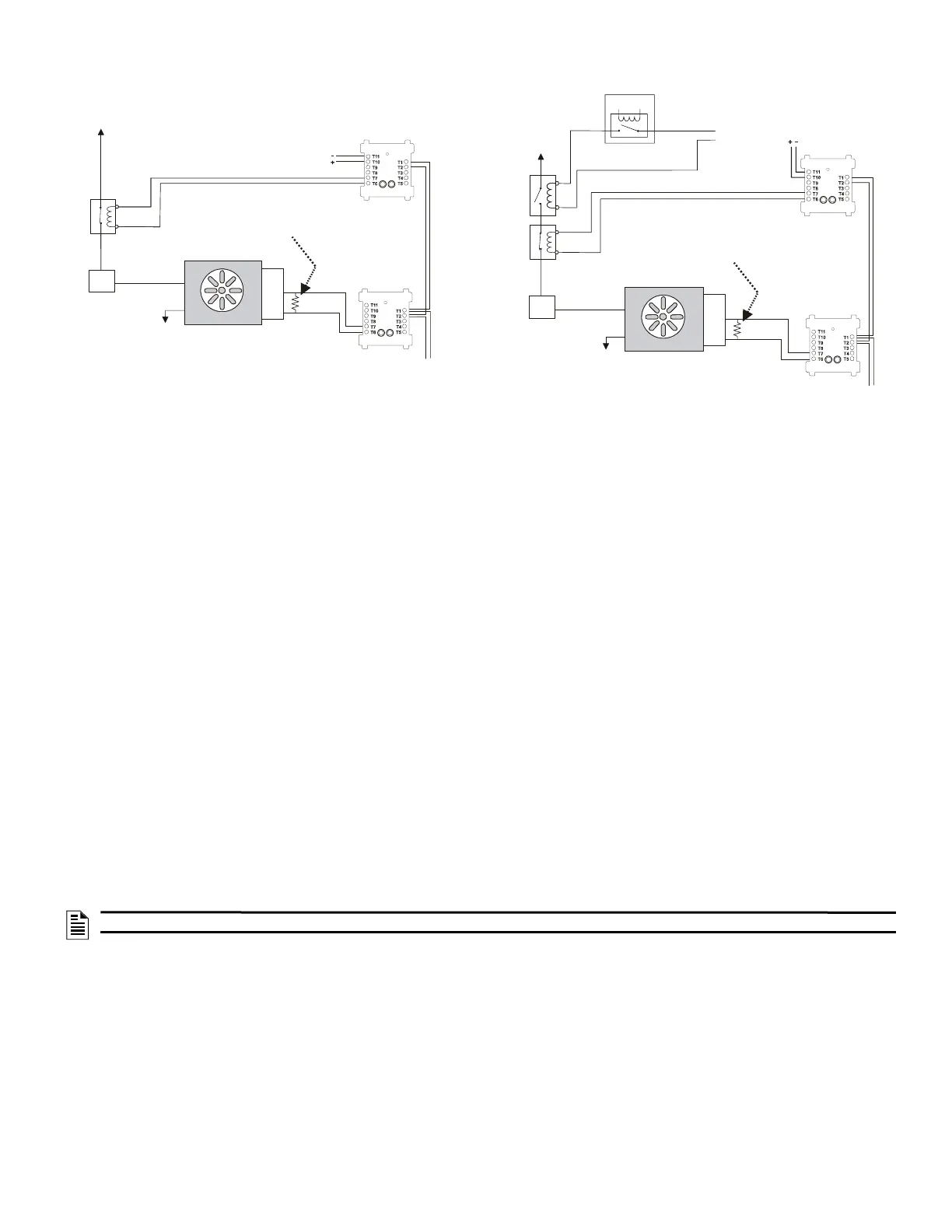
Figures 25 and 26 show wiring for a dedicated and non-dedicated smoke control system performing the same fan control functions. The system in
Figure 26 features an Energy Management System.
Refer to the SCS Series Manual, #15712, for more detailed information on the Smoke Control System.
3 Functionality
The approved functions of the NFS2-640 are listed below.
• Drift Compensation
• Remote Programming
• Extent/Limitations of Synchronization
– No synchronization across networks
• Multiple Detector Operation
Units employing multiple detector operation shall include a minimum of two detectors in each protected space and reduce the detector installation
spacing to 0.7 times the linear spacing in accordance with National Fire Alarm Code, NFPA.
• Positive Alarm Sequence
• Pre-signal
• Alarm Verification
• Two wire compatibility
• One alarm per initiating device circuit
• Polling Style Limitations
– Polling style is FlashScan or CLIP (Classic Loop Interface Protocol)
Options:
1. All detectors and modules on an SLC may be programmed as FlashScan. All detectors and modules must be FlashScan type devices.
Maximum number of devices per SLC: 159 detectors, 159 modules.
2. All detectors and modules on an SLC may be programmed as CLIP. Detectors and modules may be a mix of CLIP and FlashScan type
devices, but all must be programmed as CLIP. Maximum number of devices per SLC: 99 detectors, 99 modules.
3. All detectors may be programmed as CLIP, all modules as FlashScan, on an SLC. Detectors may be a mix of CLIP and FlashScan type
devices, modules must all be FlashScan type devices. Maximum number of devices per SLC: 99 CLIP detectors, 159 FlashScan modules.
• Manual release /abort switch interaction
– Activation of a Manual Release Switch will override Predischarge Delay and override an active Abort Release Switch, resulting in an
immediate agent release.
• NAC Reactivation
• Primary power source failure indication
• DAC Communication Format
SIA
– Contact ID
– 4 + 2 Standard
–4 + 1
–3 + 1
– 4 + 1 Ademco Express
– 4 + 2 Ademco Express
NOTE: An abort switch can only be associated with one releasing zone.
Figure 25 Dedicated Smoke Control System
SLC
Service
Disconnect
Switch
1a listed
contactor
Power
Source
Power
Return
FAN
Listed 24VDC
Power Source
SLC Control
Module
SLC Control
Module
Listed Sail
Switch
ELR-47K
(use 3.9K listed ELR with FZM-1)
N/O
COM
N/C
Figure 26 Non-Dedicated Smoke Control System
Listed
Contactor for
Energy
Management
System
1b listed
contactor
Service
Disconnect
Switch
Energy
Management
System
SLC
Power
Return
FAN
Listed Sail
Switch
SLC Control
Module
SLC Monitor
Module
ELR-47K
(use 3.9K listed ELR with FZM-1)
N/O
CO
N/C
Listed
24VDC
Power
Source
Listed
24VDC
Power
Source

 Loading...


