NFS2-640 UL Listing Document — P/N 52741LD:H9 5/19/2022 3
NOTE: When designing the cabinet layout, consider separation of power-limited (Class 2) and non-power-limited wiring as discussed in Section
“UL Power-limited Wiring Requirements”
CHS2-M2iso.wmf
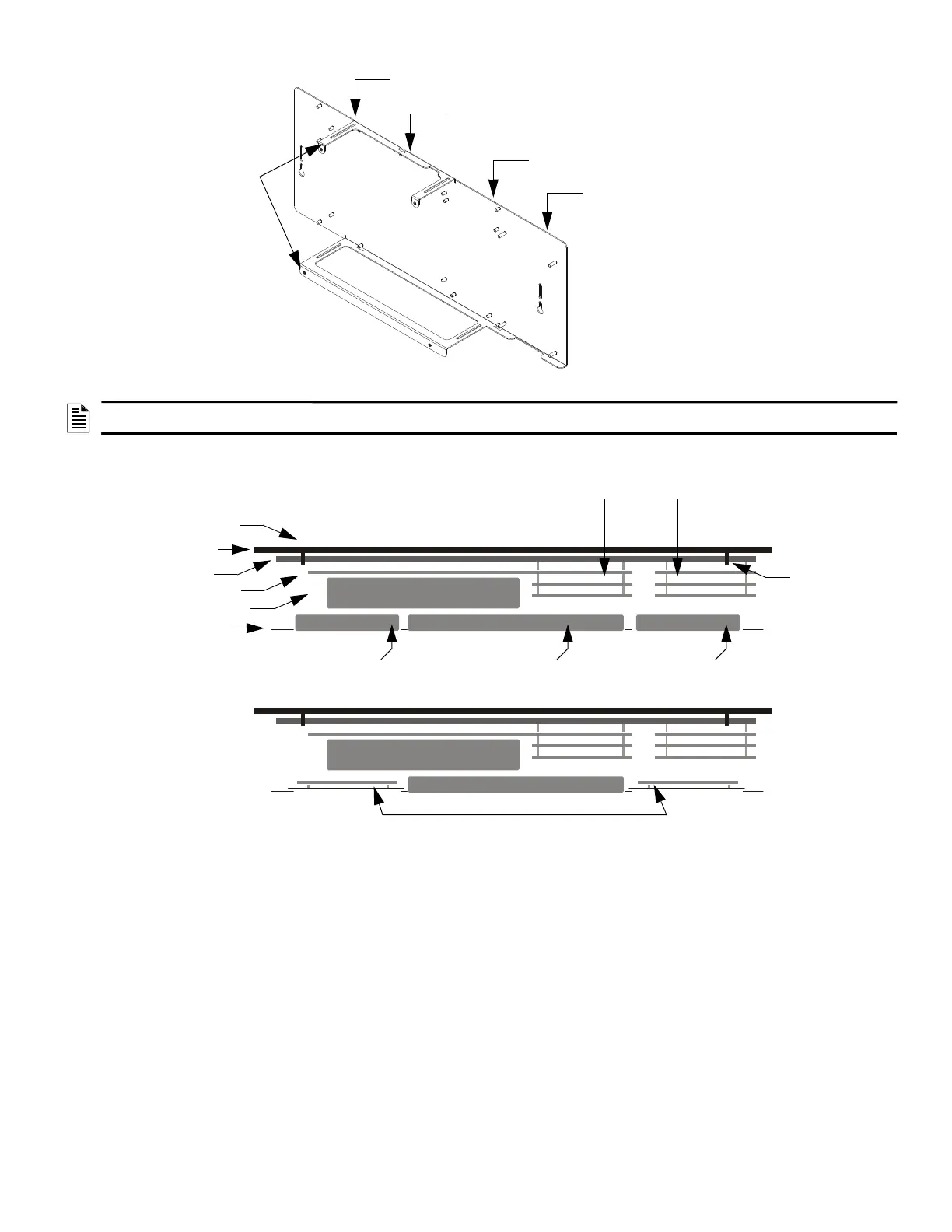
Also see Figure 2, “Top View of
NFS2-640 Chassis Mounting
Options”
Slot 1 (CPU, CPS-24, and
primary display)
Keypad/display
unit attaches to
chassis rails
Figure 1 Side View of the NFS2-640Chassis Mounting Options
Slot 2 (CPU, CPS-24,
and primary display)
Slot 3 (Mounting location
for LEM-320) or other
option board
Slot 4 Mounting location for
option boards and other
compatible peripherals
(Recommended mounting
location for fiber versions of the
NCM and HS-NCM)
CPU
CPS-24/E
DP-DISP2
(or ADP2-640
if in lower row)
Primary Display KDM-R2
or NCA-2/C (mounts to
chassis)
Right Annunciator
(mounts to dress panel)
Up to two option boards
(Including LEM-320 if used)
Up to three option boards
(2 only if longer standoffs
are used)
Option boards
Mounted on BMP-1
CHS2-M2Top.wmf
Backbox
Chassis
Keyhole
Keyhole
Left Annunciator
(mounts to dress panel)
Figure 2 Top View of NFS2-640 Chassis Mounting Options

 Loading...


