38 NFS2-640 Operations P/N 52743:L4 06/10/19
Operation of the Control Panel Operation of Special System Timers
3.13.3 How the Control Panel Indicates a Control/Relay Trouble
A trouble occurring on a control/relay module or control/relay transponder causes the control panel
to do the following:
• Produce a pulsed audible tone
• Flash the
SYSTEM TROUBLE LED
• Turn on the Trouble relay (TB4)
• Send a message to the LCD display, History buffer and installed printers FDU-80
annunciators, and CRT-2s
• Display a
TROUBL status banner and CONTROL Type Code on the LCD display, along with
information specific to the device
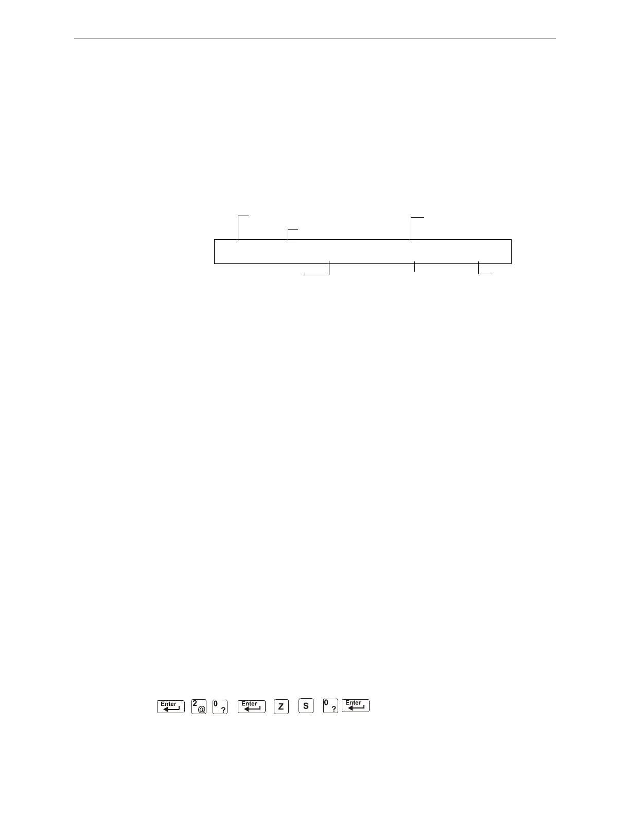
Figure 3.2 Sample of a Control/Relay Module in Trouble Message
3.13.4 How to Respond to a NAC or Control/Relay Trouble
If the control panel indicates an active NAC or Control/Relay Trouble, take the following action:
1. Press the
ACKNOWLEDGE/SCROLL DISPLAY key to silence the panel sounder and switch the
SYSTEM TROUBLE LED from flashing to steady—regardless of the number of troubles, alarms,
and supervisory signals.
2. The control panel sends an Acknowledge message to the History buffer and installed printers,
FDU-80 annunciators, and CRT-2s. Check the trouble message for the location and type of
trouble.
3. Correct the condition causing the trouble.
4. When the trouble condition is corrected, the panel will return to normal operation (indicated by
the “System Normal” message).
5. The control panel sends a “System Normal” message to the LCD display, History buffer and
installed printers, FDU-80 annunciators, and CRT-2s.
3.14 Operation of Special System Timers
3.14.1 What are System Timers?
There are user-programmable time delays for three specific functions: the Auto Silence Timer, the
Alarm Verification Timer, and the Silence Inhibit Timer. Figure 3.3 shows a sample System Func-
tion Selection screen with system timer settings. For instructions on changing system functions,
refer to the NFS2-640 Programming Manual.
3.14.2 How to View System Timer Selections
You can use the Read Status Entry option (explained in Chapter 4) to view the current selection for
the System Timers. To do so, press the keys shown below in sequence:
TROUBL CONTROL MODULE ADDR 1M044
OPEN 09:38A 041515 1M044
Status banner
Type Code
Time and date of trouble
Device Address
Type of Trouble
Custom Description for
this device location

 Loading...


