126 SCS Series Manual — P/N 15712:L 7/18/16
Ratings and Wiring Diagrams Non-dedicated Smoke Control System Wiring Diagrams
Switch group type 8 would never be needed unless redundancy in OFF and ON control were necessary. Type 8 is used for ON and OFF control
and verification of the ON state. When the CON
ON⁄OP
CM is deactivated, the CON
OFF⁄CL
CM is activated, and vice versa. The CON
ON⁄OP
CM
controls a normally closed contactor which switches power to the pressure switch. The CON
OFF⁄CL
CM controls a normally open contactor
which switches power to the pressure switch. When the CON
ON⁄OP
CM is deactivated, the contactor is closed, thus supplying power to the
pressure switch. When the CON
OFF⁄CL
CM is activated, the contactor is closed, thus supplying power to the pressure switch. Both control
modules are not necessary to supply or cut the power to the damper: one is sufficient.
Switch group type 9 would never be needed unless redundancy in
OFF and ON control were necessary. Type 9 is used for ON and OFF control
and verification of the
ON and OFF state. When the CON
ON⁄OP
CM is deactivated, the CON
OFF⁄CL
CM is activated, and vice versa. The
CON
ON⁄OP
CM controls a normally closed contactor which switches power to the pressure switch. The CON
OFF⁄CL
CM controls a normally
open contactor which switches power to the pressure switch. When the CON
ON⁄OP
CM is deactivated, the contactor is closed, thus supplying
power to the pressure switch. When the CON
OFF⁄CL
CM is activated, the contactor is closed, thus supplying power to the pressure switch.
Both control modules are not necessary to supply or cut the power to the damper: one is sufficient.
5.4 Non-dedicated Smoke Control System Wiring Diagrams
5.4.1 Fans
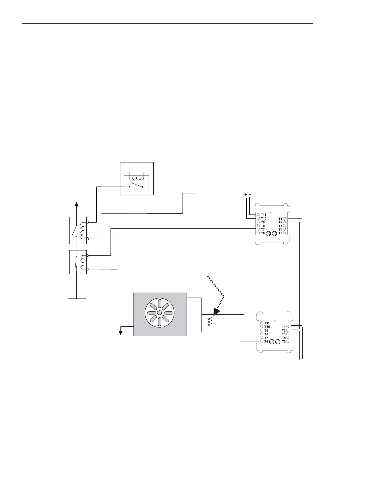
Figure 5.17 Fan Control, Non-dedicated System - FSCS Switch Group Type 1
Figure 5.17 depicts a fan in a non-dedicated system with the capability of OFF control and verification of the OFF state, switch group type 1.
In the above configuration, the CON
OFF⁄CL
CM is deactivated. The CON
OFF⁄CL
CM controls a normally closed contactor which switches
power to the fan (the contactor is used when the power being switched is greater than 24 volts). When the CON
OFF⁄CL
CM is deactivated, the
contactor is closed, thus allowing the EMS to freely control the fan. In this case the EMS is
OFF, so no power is being supplied to the fan.
When no power is supplied to the fan, the fan is
OFF and the sail switch is CLOSED, indicating no airflow in the duct. The VER
OFF⁄CL
MM
monitors the
CLOSED position of the sail switch, which would indicate when the fan is OFF. In this case the VER
OFF⁄CL
MM is activated
because the fan is
OFF due to the EMS. When the CON
OFF⁄CL
CM is activated, the normally closed contactor opens, thus cutting any power to
the fan that was being supplied by the EMS.
Power Source
1b listed
contactor
Service
Disconnect
Switch
ELR-47K
(use 3.9K listed ELR with FZM-1)
Listed
Sail
Switch
N/O
COM
N/C
Power Return
Listed
24 VDC
Power Source
FCM-1
CON
OFF/CL
CM
(deactivated)
VER
OFF/CL
MM
(activated)
fan-nf1-fs-2.wmf
SLC Loop
FAN OFF
Listed contactor
for Energy
Management
System
Energy Management System
Listed
24 VDC
Power Source
FMM-1
*If the SLC device
does not match the
one in this figure,
refer to the SLC
manual appendix,
which contains wiring
conversion charts for
type V and type H
modules.

 Loading...


