150 SCS Series Manual — P/N 15712:L 7/18/16
Ratings and Wiring Diagrams HVAC Wiring Diagrams
5.5 HVAC Wiring Diagrams
5.5.1 Fans
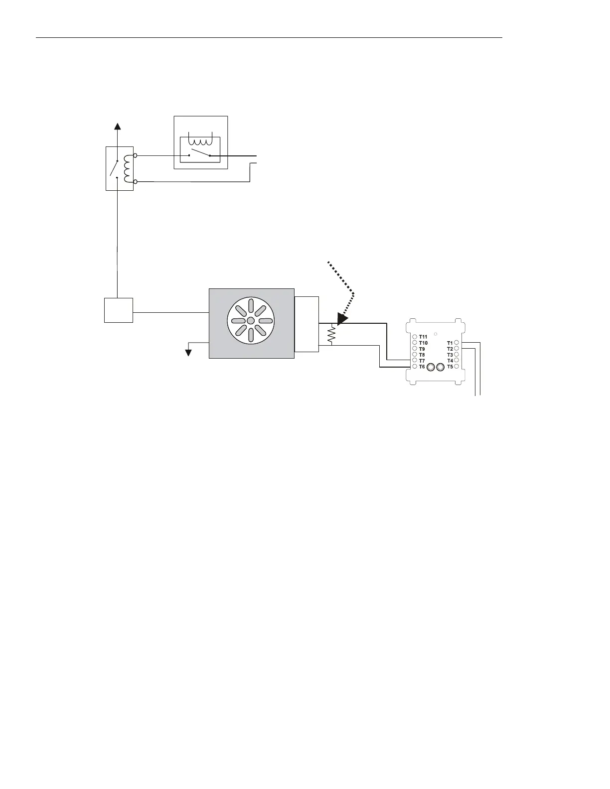
Figure 5.41 Fan Control - HVAC Switch Group Type 1
Figure 5.41 depicts a fan in an HVAC system with the capability of verifying the
OFF state, switch group type 1. In the above configuration,
the EMS is deactivated. The EMS controls a normally closed contactor which switches power to the fan. When power is not being supplied
to the fan, the fan is
OFF and the sail switch is CLOSED, indicating no airflow in the duct. The VER
OFF⁄CL
MM monitors the CLOSED position
of the sail switch, which would indicate when the fan is OFF. In this case the VER
OFF⁄CL
MM is activated because the fan is OFF and the sail
switch is
CLOSED.
Power Source
Listed contact for
Energy
Management
System
Service
Disconnect
Switch
ELR-47K
(use 3.9K listed ELR with FZM-1)
Listed
Sail
Switch
N/O
COM
N/C
Power Return
Listed
24 VDC
Power Source
VER
OFF/CL
MM
(activated)
fan-h1-fs-2.wmf
SLC Loop
FAN OFF
Energy Management System
FMM-1
*If the SLC device
does not match the
one in this figure,
refer to the SLC
manual appendix,
which contains
wiring conversion
charts for type V
and type H
modules.

 Loading...


