SCS Series Manual — P/N 15712:L 7/18/16 151
HVAC Wiring Diagrams Ratings and Wiring Diagrams
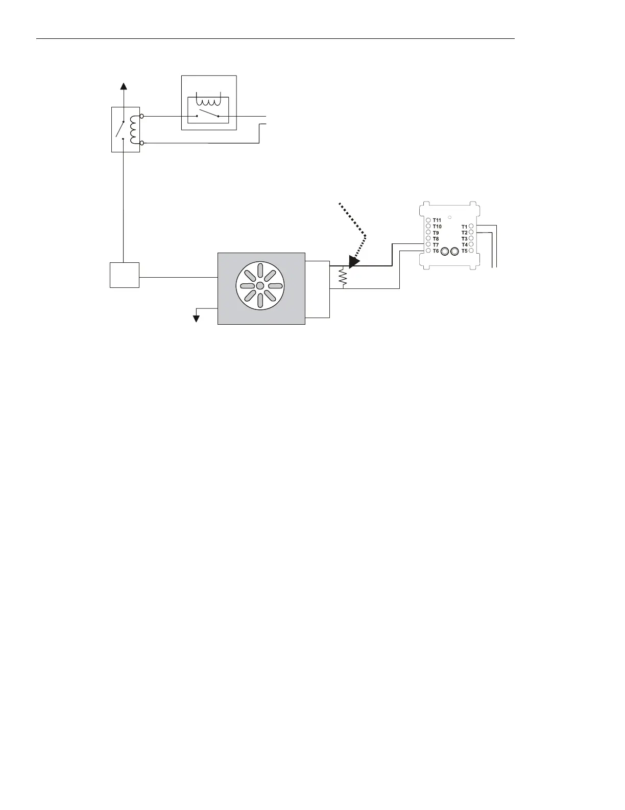
Figure 5.42 Fan Control - HVAC Switch Group Type 2
Figure 5.42 depicts a fan in an HVAC system with the capability of verifying the
ON state, switch group type 2. In the above configuration,
the EMS is deactivated. The EMS controls a normally closed contactor which switches power to the fan. When no power is supplied to the
fan, the fan is OFF and the sail switch is CLOSED, indicating no airflow in the duct. The VER
ON⁄OP
MM monitors the OPEN position of the sail
switch, which would indicate when the fan is
ON. In this case the VER
ON⁄OP
MM is deactivated because the fan is OFF and the sail switch is
CLOSED.
Switch group type 3 is for a fan that would require the capability of verifying both the
ON and OFF states. Since it is possible to determine this
information from either switch group type 1 or switch group type 2, switch group type 3 would only be necessary for redundancy in verifying
the state of the fan. For example, if switch group type 1 is used instead of switch group type 3, the
OFF state of the fan would be verified
when the MM is activated and the ON state of the fan would be verified when the monitor module is deactivated. Utilizing switch group types
1 or 2 also saves the use of an additional monitor module. Switch group type 3 would use two monitor modules to provide the same verifica-
tion as types 1 or 2.
Power Source
Service
Disconnect
Switch
ELR-47K
(use 3.9K listed ELR with FZM-1)
Listed
Sail
Switch
N/O
COM
N/C
Power Return
VER
ON/OP
MM
(deactivated)
fan-h2-fs-2.wmf
SLC Loop
FAN OFF
Listed contact for
Energy
Management
System
Energy Management System
Listed
24 VDC
Power Source
FMM-1
*If the SLC device
does not match the
one in this figure,
refer to the SLC
manual appendix,
which contains wiring
conversion charts for
type V and type H
modules.

 Loading...


