166 SCS Series Manual — P/N 15712:L 7/18/16
Ratings and Wiring Diagrams HVAC Wiring Diagrams
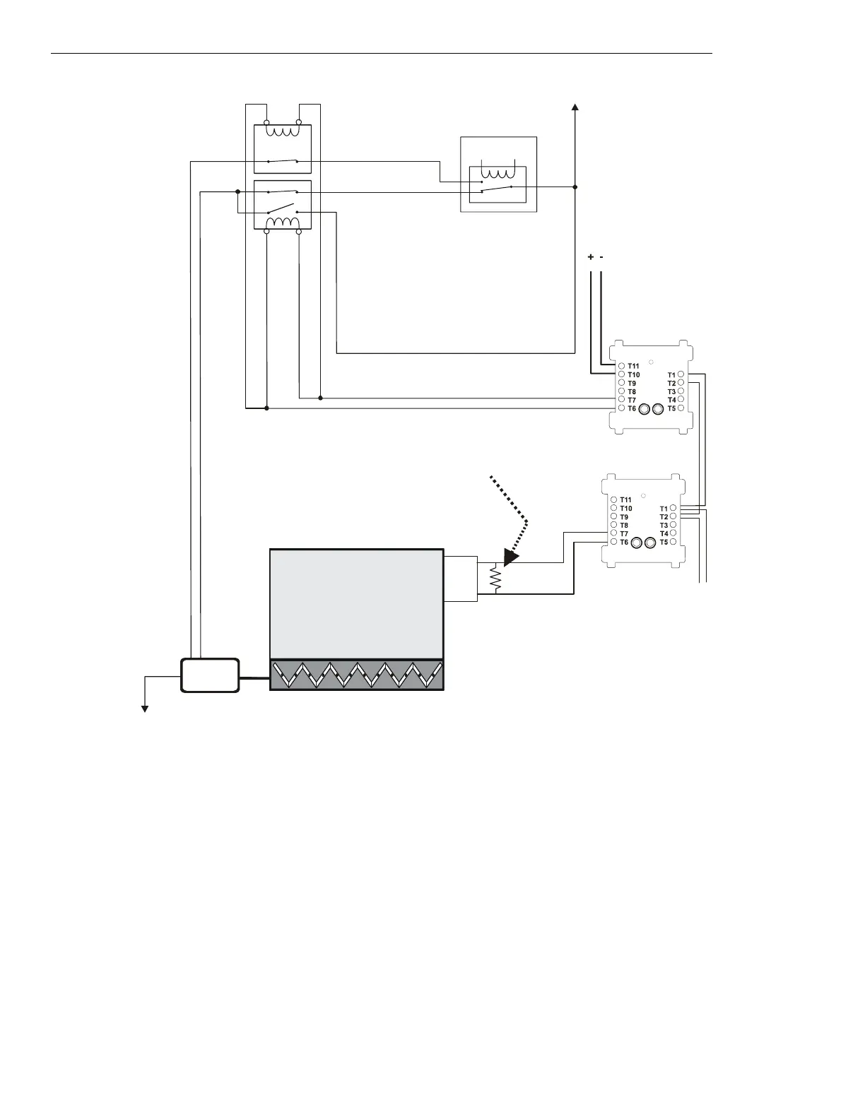
Figure 5.57 Motorized Damper Control - HVAC Switch Group Type 6
Figure 5.57 depicts a motorized damper in an HVAC system with the capability of
CLOSED control and verification of the OPEN state, switch
group type 6. In the above configuration, the CON
OFF⁄CL
CM is deactivated. The CON
OFF⁄CL
CM controls two contactors: a normally closed
contactor for the damper open power line, and a dual normally open/normally closed contactor for the damper close power. When the
CON
OFF⁄CL
CM is activated, the normally closed contactor is opened (cutting any power supplied by the EMS to the damper open power
line), the normally closed portion of the dual contactor is opened (cutting any power supplied by the EMS to the damper closed power line),
and the normally open portion of the dual contactor is closed, thus supplying power to close the damper. When the CON
OFF⁄CL
CM is deacti-
vated, the EMS is free to control the damper. The EMS is currently supplying power to the damper closed power line.
When power is supplied to the damper closed power line, the damper closes. When the damper completely closes, the damper closed limit
switch is
CLOSED, indicating that the damper is in the CLOSED position.
The VER
ON⁄OP
MM monitors the CLOSED position of the damper open limit switch. In this case the VER
ON⁄OP
MM is deactivated because the
damper is
CLOSED.
Power Source
Damper
Open
Power
ELR-47K
(use 3.9K listed ELR with FZM-1)
Power Return
Listed
24 VDC
Power Source
DMO-h6a-fs-2.wmf
SLC Loop
Damper
Closed
Power
AC
MOTOR
DAMPER
CLOSED
FCM-1
CON
OFF/CL
CM
(deactivated)
Energy
Management
System
1b listed contact
1a, 1b
listed
contact
FMM-1
VER
ON⁄OP
MM
(deactivated)
N/O
COM
Limit Switch
for open
position
*If the SLC device
does not match the
one in this figure,
refer to the SLC
manual appendix,
which contains
wiring conversion
charts for type V
and type H
modules.
 Loading...


