172 SCS Series Manual — P/N 15712:L 7/18/16
Ratings and Wiring Diagrams HVAC Wiring Diagrams
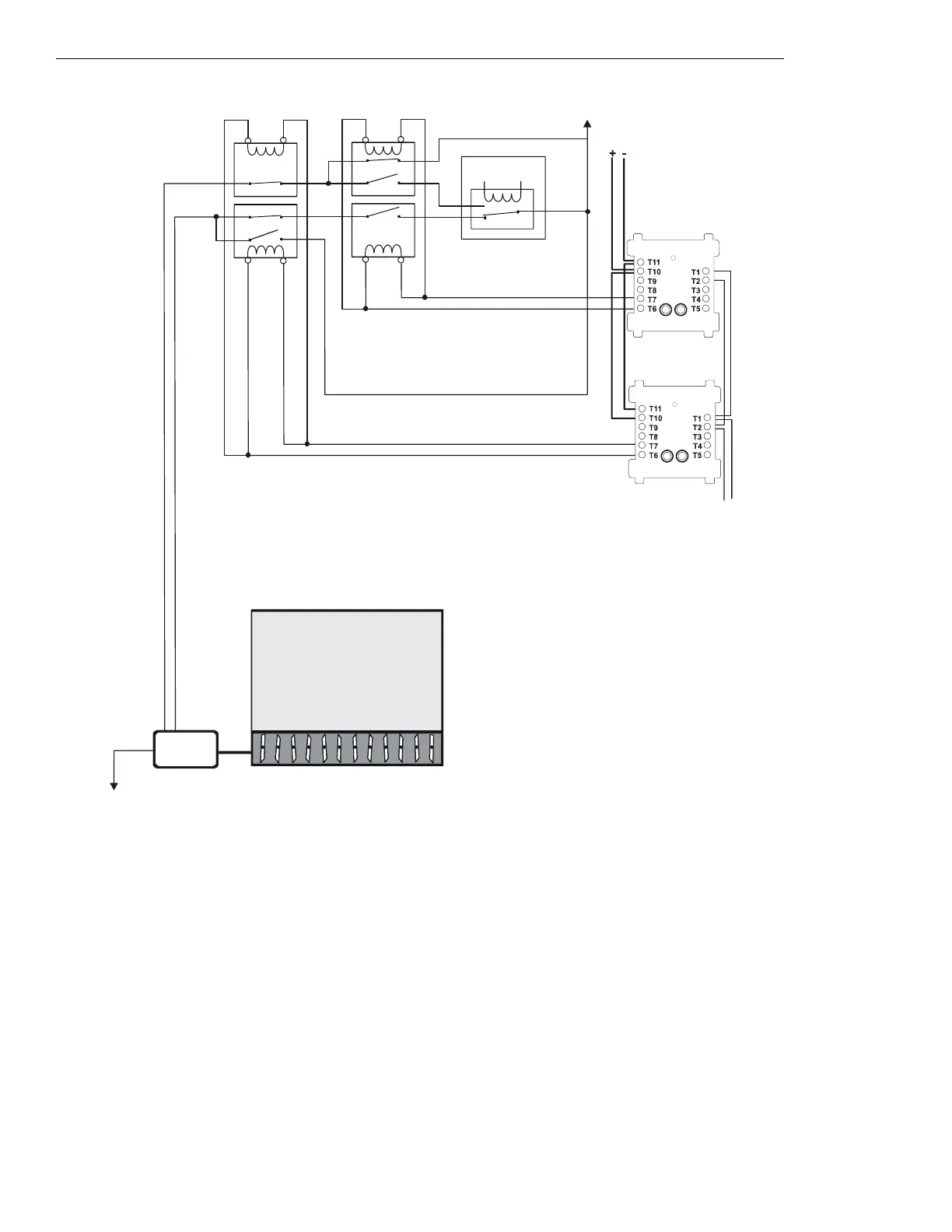
Figure 5.63 Motorized Damper Control - HVAC Switch Group Type 12
Figure 5.63 depicts a motorized damper in an HVAC system with the capability of
OPEN and CLOSED control, switch group type 12. In the
above configuration, the CON
ON⁄OP
CM is activated and the CON
OFF⁄CL
CM is deactivated. Under normal operation (non-smoke control
mode) both control modules would be deactivated, allowing the EMS system to freely control the damper. The CON
ON⁄OP
CM controls two
contactors: a normally closed contactor for the damper closed power line, and a dual normally open/normally closed contactor for the
damper open power line. The CON
OFF⁄CL
CM controls two contactors: a normally closed contactor for the damper open power line, and a
dual normally open/normally closed contactor for the damper closed power line. When the CON
ON⁄OP
CM is activated, the CON
OFF⁄CL
CM is
deactivated, and vice versa. When the CON
ON⁄OP
CM is activated, the normally closed contactor is opened (cutting any power supplied by
the EMS to the damper closed power line), the normally closed portion of the dual contactor is opened (cutting any power supplied by the
EMS to the damper open power line), and the normally open portion of the dual contactor is closed, thus supplying power to open the
damper.
Power Source
Damper
Open
Power
Power Return
Listed
24 VDC
Power Source
DMO-h12a-fs-2.wmf
SLC Loop
CON
ON/OP
CM
(activated)
Damper
Closed
Power
AC
MOTOR
DAMPER
OPEN
FCM-1
FCM-1
CON
OFF/CL
CM
(deactivated)
1a, 1b listed contact
1b listed
contact
Energy
Management
System
1b listed contact
1b, 1a
listed
contact
*If the SLC device
does not match the
one in this figure,
refer to the SLC
manual appendix,
which contains
wiring conversion
charts for type V
and type H
modules.
 Loading...


