184 SCS Series Manual — P/N 15712:L 7/18/16
Ratings and Wiring Diagrams HVAC Wiring Diagrams
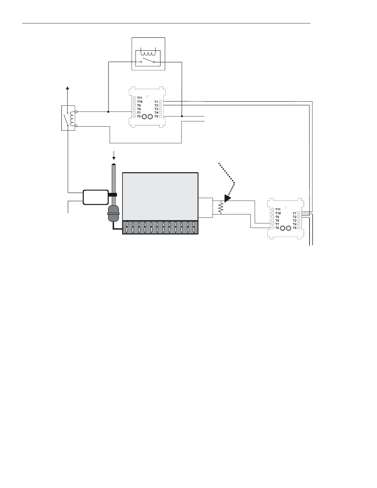
Figure 5.76 EP Damper Control - HVAC Switch Group Type 10
Figure 5.76 depicts an EP damper in an HVAC system with the capability of OPEN control and verification of the OPEN state, switch group
type 10. In the above configuration, the CON
ON⁄OP
CM is activated. The CON
ON⁄OP
CM controls a normally closed contactor for the pressure
switch power line. When the CON
ON⁄OP
CM is activated, the normally closed contactor is opened. When the contactor opens, power is cut
from the pressure switch which allows airflow to open the damper. When the CON
ON⁄OP
CM is deactivated, the EMS is free to control the
damper. The EMS is currently being overridden by the CON
ON⁄OP
CM.
When power is cut from the pressure switch, the damper opens. When the damper completely opens, the damper open limit switch is
CLOSED
and the damper closed limit switch is
OPEN, indicating that the damper is in the OPEN position. The VER
ON⁄OP
MM monitors the CLOSED
position of the damper open limit switch. In this case the VER
ON⁄OP
MM is activated because the damper is OPEN.
FMM-1
Airflow
PRESSURE
SWITCH
SMOKE
DAMPER
OPEN
Power
Source
Listed
24 VDC
Power Source
SLC Loop
DEP-h10A-fs-2.wmf
Power
Return
VER
ON⁄OP
MM
(activated)
N/O
COM
Limit Switch
for closed
position
ELR-47K
(use 3.9K listed ELR with FZM-1)
Pneumatic
Tubing
Energy
Management
System
1b listed
contactor
FRM-1
CON
ON/OP
CM
(activated)
COM
N/O
*If the SLC device
does not match the
one in this figure, refer
to the SLC manual
appendix, which
contains wiring
conversion charts for
type V and type H
modules.

 Loading...


