EasyManua.ls Logo

Honeywell NOTIFIER SCS Series User Manual

Honeywell NOTIFIER SCS Series
210 pages
To Next Page IconTo Next Page
To Previous Page IconTo Previous Page
Page #203 background imageLoading...
Page #203 background image
SCS Series Manual — P/N 15712:L 7/18/16 203
Multiple Smoke Control Station Special Applications
See NCA-2 Manual for instructions on programming the following example.
NCA-2 (N1)
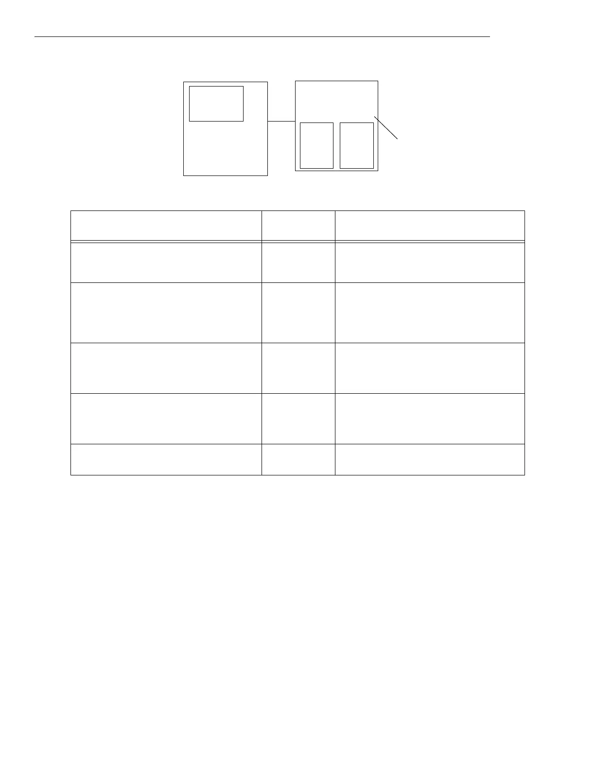
Figure C.1 Programming Example 1: Primary Panel, Normally in Control, Enabled
Custom Graphics
Annunciator
Programming
Visual
Indicators Notes
ZL498 = OR(SCSDIS(A25),N2ZL498) Primary SCS
Disabled
ZL498 will be active when the primary’s
enable/disable switch is disabled and the secondary
NCA-2 SCS is enabled/disabled.
ZL499 = OR(AUTO(A25)) -- Required for Multiple Smoke Control Systems
applications; monitors the Auto status of the SCS-
8L (designated as A25 in this example).
Logic zone address must be lower than that of the
MSCS Control Zone.
ZL500 = AND(NOT(SCSDIS(A25)),NOT(N2ZL500)) Primary SCS
Active
ZL500 identifies the MSCS Control Zone of the
primary NCA-2. This logic zone will be active when
the primary’s enable/disable switch (SCSDIS) is
enabled and the secondary NCA-2 is disabled.
ZL501 = AND(ZL499,N2ZL499) -- Required to track when the SCS-8L is in Auto. SCS-
8L must use the next consecutive logic zone
address after the MSCS Control Zone of the primary
NCA-2.
N2ZL500 Secondary SCS
Active
N2ZL500 identifies the MSCS Control Zone of the
secondary NCA-2.
User interface for
Primary MSCS:
Enable/Disable switch
Control switches
Visual indicators
Primary MSCS Panel
SCS-8L
(A25)
LDM-32

Table of Contents

Question and Answer IconNeed help?

Do you have a question about the Honeywell NOTIFIER SCS Series and is the answer not in the manual?

Honeywell NOTIFIER SCS Series Specifications

General IconGeneral
BrandHoneywell
ModelNOTIFIER SCS Series
CategoryControl Unit
LanguageEnglish

Summary

Fire Alarm & Emergency Communication System Limitations

Installation Precautions

FCC Warning

Warning regarding FCC rules for radio frequency energy emissions.

Canadian Requirements

Statement on digital apparatus meeting Canadian radio noise emission limits.

Section 1: About This Manual

Standards and Other Documents

Lists NFPA, UL, and other standards relevant to the fire alarm control panel.

UL 864 Compliance

Details compliance with UL 864 9th Edition for control units and accessories.

Supplemental Documentation

Lists other documents and compatible devices referenced in the manual.

Cautions and Warnings

Explains the meaning of caution and warning notations used throughout the manual.

Manual Conventions

Defines terms and conventions used within the manual for clarity.

Section 2: Concepts of Smoke Control

Introduction, Definitions, and Abbreviations

Overview of smoke control concepts, components, relevant standards, definitions, and abbreviations.

Smoke Movement Factors

Explains factors influencing smoke movement: stack effect, buoyancy, expansion, wind, elevator piston, HVAC.

Smoke Control Principles

Details principles of smoke containment (pressurization, airflow), purging, and door-opening forces.

System Components and Types

Covers general system components (HVAC, control, initiating) and types (dedicated, non-dedicated, zoned, stairtower, elevator).

Basic System Operation

Explains fundamental operation of smoke control systems involving fans, dampers, and control scenarios.

Section 3: The SCS/SCE

Introduction and Hardware Features

Introduces SCS/SCE, its hardware, compatibility, software versions, and related modules.

SCS-8/SCE-8/SCS-8L/SCE-8L Installation and Configuration

Covers installation, configuration, dipswitch settings, addressing, mounting, and wiring for SCS/SCE modules.

SCS Programming

Details programming procedures for SCS modules with various FACP systems (NFS, NCA, AM2020) and modes (FSCS, HVAC).

Section 4: Restrictions

Equipment

Lists restrictions and recommendations for equipment used in smoke control systems, including dampers and detectors.

Installation

Specifies restrictions related to dipswitch settings, EIA-485 circuits, wiring distances, and enclosures.

Operation

Outlines operational restrictions for FSCS mode, manual override, and HVAC mode limitations.

Programming

Details programming restrictions for unused switch groups, SCE usage, and control module settings.

Testing

States the requirement for weekly automatic testing of dedicated smoke control systems by the FACP.

Section 5: Ratings and Wiring Diagrams

Introduction and Air Flow Switches

Introduces monitor/control modules, wiring diagrams, and lists relevant air flow switches.

Dedicated Smoke Control System Wiring Diagrams

Illustrates wiring for fans, motorized dampers, and EP dampers in dedicated FSCS mode.

Non-dedicated Smoke Control System Wiring Diagrams

Shows wiring for fans, motorized dampers, and EP dampers in non-dedicated FSCS mode.

HVAC Wiring Diagrams

Presents wiring diagrams for fans, motorized dampers, and EP dampers in HVAC mode.

Appendix A: AM2020/AFP1010 Control-By-Event

Introduction and Definitions

Introduces CBE programming and explains lists, equations, and operators (OR, AND, NOT, XZONE, DEL, SDEL, TIM).

Size Limitations and Null Control-By-Event

Details CBE byte limitations, calculation formulas, and the concept of Null Control-By-Event.

Programming Examples

Provides examples illustrating basic programming tasks for notification appliances and control modules.

Appendix B: Miscellaneous Information

Control-By-Event Information and Worksheets

Provides CBE info for NFS/NCA, NCA-2 operation, and SCS/SCE worksheets for system design.

Compatibility with Other Systems

States compatibility of smoke control modules with XLS3000 system and NFS2-3030 programming.

Appendix C: Special Applications

Mode A and Mode B Operation

Describes Mode A (classic SCS) and Mode B operation, including independent switch-group and CBE lockout.

Multiple Smoke Control Station and Read Status

Covers multiple station configurations, programming, and reading SCS-8L status from NFS2-3030/NCA-2.

Pairing and Custom Graphic Annunciators

Explains SCS module pairing and using logic operators for custom graphic annunciator displays.

Related product manuals