44 SCS Series Manual — P/N 15712:L 7/18/16
The SCS⁄SCE SCS-8⁄SCE-8 Installation
Wiring Specifications
The EIA-485 circuit cannot be T-Tapped; it must be wired in a continuous fashion from the control panel to
the SCS-8. The maximum wiring distance between the panel and the last SCS-8 or annunciator is 6,000 feet
@ 16 AWG. All SCS-8/ SCE-8 modules must be contained in the same room with the FACP/INA/NCA in
FSCS mode. The wiring size must be a 12 to 18 AWG twisted pair cable having a Characteristic Impedance
of 120 ohms, +/- 20% (shielded cable is recommended). Limit the total wire resistance to 100 ohms on the EIA-485 circuit, and 10 ohms on
the SCS-8 power circuit. Do not run cable adjacent to, or in the same conduit as, 120 volts AC service, noisy electrical circuits that are pow-
ering mechanical bells or horns, audio circuits above 25 volts (RMS), motor control circuits, or SCR power circuits.
Terminal Wiring
The following should be considered when connecting terminal wiring:
• Do not “T-Tap” the EIA-485 circuit. It will not function properly. Wire it as shown in Figure 3.14.
• AM2020/AFP-1010/INA - Install the built-in 120 ohm resistor on the SCS-8 module if it is located at the physical end of the EIA-485
circuit, by turning ON dipswitch 8 on the SCS-8. Turn OFF dipswitch 8 on all other SCS-8 modules. If an EIA-485 device other than an
SCS-8⁄SCE-8 is at the physical end of the EIA-485 loop, install a R-120 resistor across the EIA-485 out terminals of the device and
ensure that dipswitch 8 is turned OFF on all SCS-8 modules.
• Connect Earth Ground to a mounting screw on the backbox or cabinet.
• Connect 24 VDC Power to the SCS-8. This power need not be supervised by a power supervision relay since it is inherently supervised
by the control panel (loss of communications is registered during loss of power to the SCS-8).
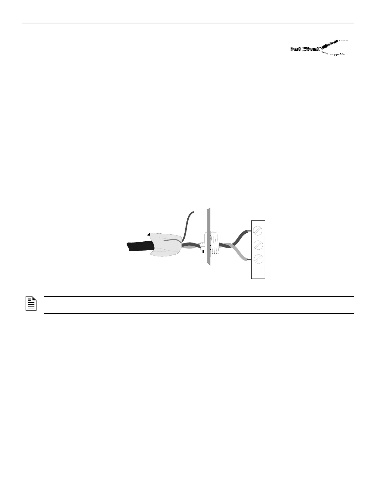
When the EIA-485 shield is in conduit: Connect it to the system reference (system common). The shield can enter the cabinet, but must be
insulated from the cabinet (no electrical contact). Between Smoke Control Stations, wire-nut multiple shields together and insulate. Treat the
shield like a system wire making certain it does not come in contact with other wires or earth ground.
When the EIA-485 shield is not in conduit: Terminate the shield at the outside of the FACP backbox (ground). Do not allow the shield to
enter or even touch the cabinet. Between Smoke Control Stations, wire-nut multiple shields together outside of the respective enclosures.
Enclosure
SCS-8
Terminal
Block
Figure 3.12 Terminating the Shield
NOTE: All enclosures, including the FACP backbox, must be connected to earth ground! Never use the shield for grounding purposes.
Terminate the EIA-485 shield at the Fire Alarm Control Panel only.

 Loading...


