SCS Series Manual — P/N 15712:L 7/18/16 89
Building-Specific Operation and Programming Examples The SCS⁄SCE
By referencing Table 3.3 the corresponding switch group type can be obtained.
For each capability a device is to have, a control or monitor module will be necessary at the fan or damper. Each control (CON) capability
will require a control module (CM) and each verification (VER) capability will require a monitor module (MM).
For our example a total of 36 CMs and 68 MMs will be required.
The next step is to determine the configurations for the SCSs and/or SCEs to be used. Although there are many ways to configure the
SCS⁄SCE pairs, the following configuration will be used for this example:
• The four type 5 fans will be on one SCS with four switch groups unused.
• The 32 type 6 dampers will be on two SCS⁄SCE pairs.
The configurations selected on the previous page are reference numbers 11 and 12 respectively from Table 3.5 (12 will be used twice). The
dipswitch settings from Table 3.5 for each SCS should be noted for installation purposes at this time.
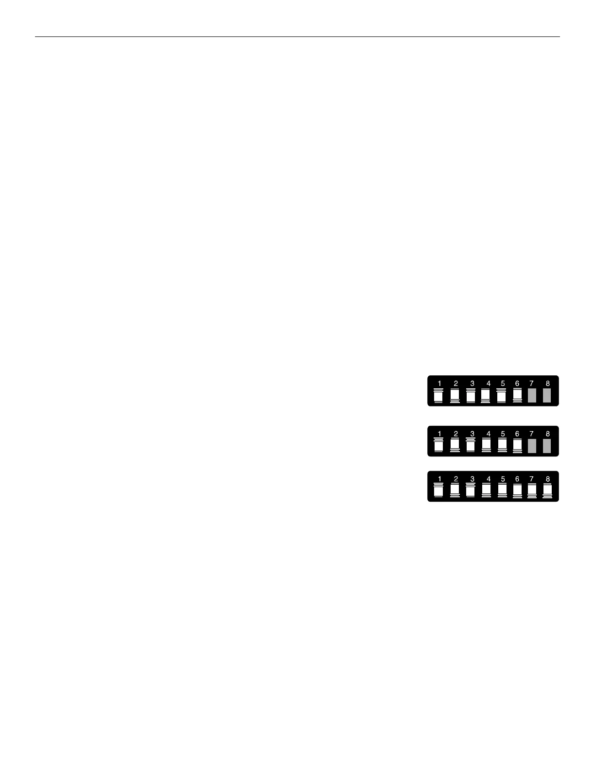
Dipswitches 1-5 from reference number 11 of Table 3.5 set all the switch groups for switch
group type 5. Dipswitch 6 is in the ON position to select the FSCS mode. Dipswitch 7 is in the
ON position to select Dedicated System operation. Dipswitch 8 is OFF so that the end-of-line
termination resistor is not installed. Dipswitch 8 is only set to the ON position when the particu-
lar SCS is the last device on the EIA-485 data line.
Dipswitches 1-5 from reference number 12 of Table 3.5 set all the switch groups for switch
group type 6. Dipswitch 6 is in the ON position to select the FSCS mode. Dipswitch 7 is in the
ON position to select Dedicated System operation. Dipswitch 8 is OFF for the first SCS⁄SCE
pair so that the end-of-line termination resistor is not installed. Dipswitch 8 is ON for the sec-
ond SCS⁄SCE pair so that the end-of-line termination resistor is installed. Dipswitch 8 is only
set to the ON position when the particular SCS is the last device on the EIA-485 data line.
After the dipswitch settings have been determined, an EIA-485 device address for each SCS
must be determined. As stated before, there are 32 available addresses. So if no other EIA-485
devices are present on the data line (such as annunciators) the maximum number of SCS⁄SCE
pairs allowed is 32. For our example, we only need three available addresses. Let us assume that addresses 5, 6, and 7 are available. As
shown in Table 3.4 and Figure 3.4, set the dipswitches and addresses of each SCS.
Stairtower Fan (1): Switch Group Type 5 (CON
ON⁄OP
and VER
ON⁄OP
)
Elevator Fan (1): Switch Group Type 5 (CON
ON⁄OP
and VER
ON⁄OP
)
Supply Fan (1): Switch Group Type 5 (CON
ON⁄OP
and VER
ON⁄OP
)
Exhaust Fan (1): Switch Group Type 5 (CON
ON⁄OP
and VER
ON⁄OP
)
Supply Dampers (16): Switch Group Type 6 (CON
ON⁄OP
, VER
ON⁄OP
and VER
OFF⁄CL
)
Exhaust Dampers (16): Switch Group Type 6 (CON
ON⁄OP
, VER
ON⁄OP
and VER
OFF⁄CL
)
Stairtower Fan (1): CON
ON⁄OP
and VER
ON⁄OP
1 - CM 1 - MM
Elevator Fan (1): CON
ON⁄OP
and VER
ON⁄OP
1 - CM 1 - MM
Supply Fan (1): CON
ON⁄OP
and VER
ON⁄OP
1 - CM 1 - MM
Exhaust Fan (1): CON
ON⁄OP
and VER
ON⁄OP
1 - CM 1 - MM
Supply Dampers (16): CON
ON⁄OP
, VER
ON⁄OP
and VER
OFF⁄CL
16 - CM 32 - MM
Exhaust Dampers (16): CON
ON⁄OP
, VER
ON⁄OP
and VER
OFF⁄CL
16 - CM 32 - MM

 Loading...


