94 SCS Series Manual — P/N 15712:L 7/18/16
The SCS⁄SCE Building-Specific Operation and Programming Examples
modules would be L3M4, L3M5, L3M7 and L3M8). All supply dampers on non-fire floors must be opened when a fire is detected. How-
ever, the dampers are not to open in response to the manual pull station. If we use the eight reverse software zones that were defined earlier
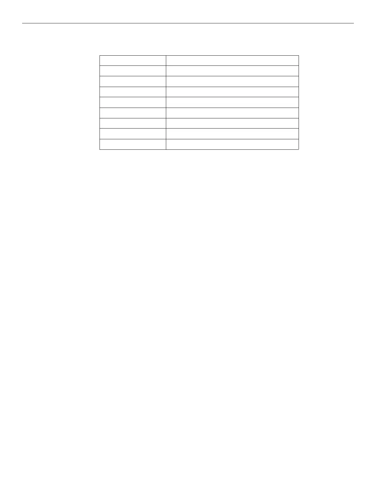
(Z201-Z208), the CBE equation for the control modules controlling the supply dampers on each floor would be:
If a device on floor 6, with the exception of the manual pull station, becomes ACTIVE, the CBE equation for Z206 will become TRUE. As a
result, all equations that contain Z206 in them will be TRUE. When the equations become TRUE, the CON
ON⁄OP
CMs become ACTIVE and
open all the dampers except those on floor 6. The CBE equations for L6M3 and L6M6 are the only equations that will be FALSE in this case
and subsequently not open the dampers on floor 6.
The next set of equations to be determined is for the exhaust dampers. There is one control module per damper with the capability to open
the dampers (the control module is referred to as a CON
ON⁄OP
CM). Let us assume that the two CON
ON⁄OP
CMs for the exhaust dampers are
wired on the SLC loop for the floor that they serve. For instance the two control modules for floor 5 would be L5M9 and L5M12 (the four
monitor modules would be L3M10, L3M11, L3M13 and L3M14). The two exhaust dampers per floor are to open when a fire is detected on
that floor. However, the dampers are not to open in response to the manual pull station. The CBE equation for the CON
ON⁄OP
CMs controlling
the exhaust dampers on each floor would be:
OR(Z20x)
where x is one of the eight reverse software zones corresponding to the appropriate floor. If a device on floor 6, with the exception of the
manual pull station, becomes ACTIVE, the CBE equation for Z206 will become TRUE. This would cause the equations for L6M9 and
L6M12 to become TRUE. When these equations become TRUE the CON
ON⁄OP
CMs are ACTIVE and open the two dampers.
The CBE equations for the supply and exhaust fans are a little more complex than the equations previously discussed. In order to prevent
damage to ductwork, the supply and exhaust fans should not be turned on until the dampers that need to opened are open and the dampers
that need to be closed are closed. So, not only do the CBE equations have to check when a detector is in alarm, but they have to check the
monitor modules on the dampers to ensure the open/closed position. The supply fan has one control module for controlling the ON capability
of the supply fan and the exhaust fan has one control module for controlling the ON capability of the exhaust fan (both control modules are
referred to as CON
ON⁄OP
CMs). Let us assume that both CON
ON⁄OP
CMs are wired on SLC loop 9 of the FACP. These would be the fifth and
seventh modules on this loop. The CON
ON⁄OP
CM for the supply fan would be L9M5 and the control module for the exhaust fan would be
L9M7 (the monitor modules would be L9M6 and L9M8 respectively).
There are two monitor modules per damper and there are four dampers per floor (two supply and two exhaust). The supply dampers must be
checked to make sure that at least one of the dampers is open. The exhaust dampers must be checked to ensure that the damper on the fire
floor is open. Let us assume that the four monitor modules for the dampers are wired on the SLC loop for the floor that they serve. For
instance the four monitor modules of the supply dampers for floor 5 would be L5M4, L5M5, L5M7 and L5M8 and the four monitor modules
of the exhaust dampers for floor 5 would be L5M10, L5M11, L5M13 and L5M14 (where LxM4 and LxM7 are the VER
ON⁄OP
MMs for the
supply damper, LxM5 and LxM8 are the VER
OFF⁄CL
MMs for the supply damper, LxM10 and LxM13 are the VER
ON⁄OP
MMs for the
exhaust damper, and LxM11 and LxM14 are the VER
OFF⁄CL
MMs for the exhaust damper).
The CBE equation for the supply fan involve the creation of eight more reverse software zones (Z211, Z212, Z213, Z214, Z215, Z216, Z217,
and Z218), one for each floor, and each programmed with a CBE of:
AND(LxM4 LxM7)
This equation is TRUE when the supply dampers on floor x are open. The CBE equation for L9M5 would be:
AND(Z20x AND(LxM5 LxM8) OR(Z211 Z212 Z213 Z214 Z215 Z216 Z217 Z218))
where x is one of the eight loops (1-8) that corresponds to the appropriate floor. If any device in the building becomes ACTIVE as a result of
a fire (except the manual pull stations) AND the supply dampers are closed for that floor AND at least one pair of dampers on the other
floors are open, then the equation for L9M5 would become TRUE. This would cause the control module to be ACTIVE. When the control
module becomes active the supply fan will turn on.
module #: CBE equation:
L1M3 and L1M6 OR(Z202 Z203 Z204 Z205 Z206 Z207 Z208)
L2M3 and L2M6 OR(Z201 Z203 Z204 Z205 Z206 Z207 Z208)
L3M3 and L3M6 OR(Z201 Z202 Z204 Z205 Z206 Z207 Z208)
L4M3 and L4M6 OR(Z201 Z202 Z203 Z205 Z206 Z207 Z208)
L5M3 and L5M6 OR(Z201 Z202 Z203 Z204 Z206 Z207 Z208)
L6M3 and L6M6 OR(Z201 Z202 Z203 Z204 Z205 Z207 Z208)
L7M3 and L7M6 OR(Z201 Z202 Z203 Z204 Z205 Z206 Z208)
L8M3 and L8M6 OR(Z201 Z202 Z203 Z204 Z205 Z206 Z207)

 Loading...


