22 PW-7000 Two-Reader Module Installation Guide, Document 800-25676V1
Input 0 Com
Pin #2
Input 1
Pin #3
Input 1 Com
Pin #4
Relay 0 No
Pin #5
Relay 0 Com
Pin #6
Relay 0 NC
Pin #7
Relay 1 No
Pin #8
Relay 1 Com
Pin #9
Relay 1 NC
Pin #10
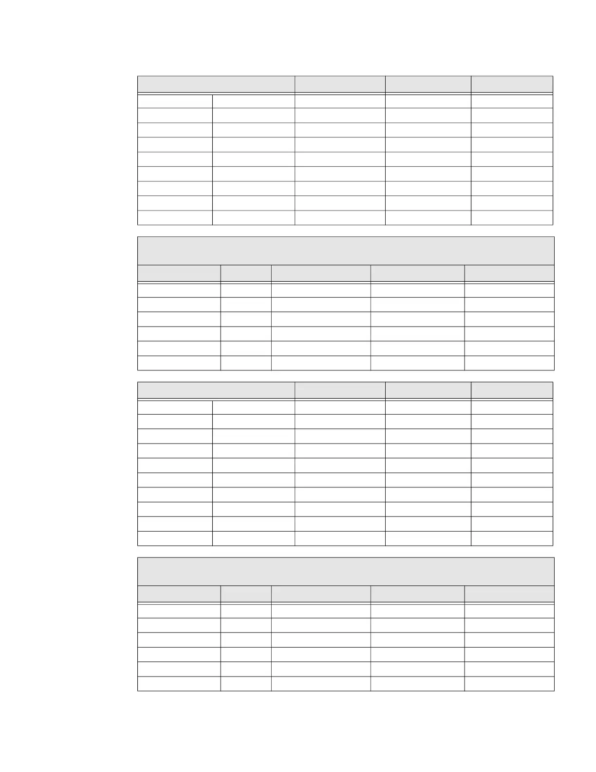
Reader 0
Pro-Watch Reader 0 (the reader address used in the Pro-Watch hardware setup)
VDC Select J2 5 Volt Connected Cable # Cable Destination Conductor Color
DC Out ( + )
Pin #1
Red LED
Pin #2
Beeper Ctrl
Pin #3
Data - 1
Pin #4
Data - 0
Pin #5
Common
Pin #6
Door 2 Input / Output Connected Cable # Cable Destination Conductor Color
Input 2
Pin #1
Input 2 Com
Pin #2
Input 3
Pin #3
Input 3 Com
Pin #4
Relay 2 No
Pin #5
Relay 2 Com
Pin #6
Relay 2 NC
Pin #7
Relay 3 No
Pin #8
Relay 3 Com
Pin #9
Relay 3 NC
Pin #10
Reader 2
Pro-Watch Reader 1 (the reader address used in the Pro-Watch hardware setup)
VDC Select J2 5 Volt Connected Cable # Cable Destination Conductor Color
DC Out ( + )
Pin #1
Red LED
Pin #2
Beeper Ctrl
Pin #3
Data - 1
Pin #4
Data - 0
Pin #5
Common
Pin #6
Door 1 Input / Output Connected Cable # Cable Destination Conductor Color
 Loading...