5 69-2500—01
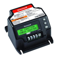
R7284 SERIES
R7284 Flame Strength (Basic Interface)
During normal operation and when the R7284 is in the Running
state, the LED will show CAD cell resistance. See Table 2.
Error History (Basic Interface)
The last two errors are available for display on the LED:
• Pressing the up arrow button displays the most recent error.
• Pressing the down arrow button displays the next most recent
error.
Once the up or down arrow is pushed, the LED will display the
most recent or next most recent alarm by blinking the error code.
See Table 3.
R7284 Error Codes (Basic Interface)
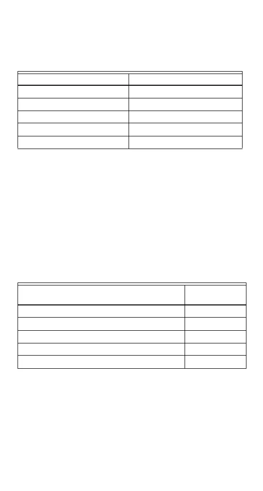
Table 2. Flame Strength Indication.
Flame Strength Indication Number of 1/2 sec flashes
Cad Cell less than 400Ω 1
400Ω < Cad Cell < 800Ω 2
800Ω < Cad Cell < 1600Ω 3
1600Ω < Cad Cell < 6100Ω 4
Cad Cell > 6100Ω None
Table 3. Error Codes.
Error Codes
Number of 1/4
sec flashes
No ignition / Late ignition 1
Max flame losses / Cad Cell high while running 2
Flame out of sequence 3
Low Voltage / EnviraCOM™ error 4
Internal Error 5
 Loading...