Do you have a question about the Honeywell MC ToolKit and is the answer not in the manual?
Details Honeywell's warranty policy, remedy procedures, and limitations of liability for its products.
Provides contact information for Honeywell technical assistance via World Wide Web and telephone.
Outlines the manual's intent to facilitate MC Toolkit use and the assumed user skill level.
Describes the MC Toolkit package, its software components, and the features of MCT101 and MCT202 versions.
Discusses factors to consider before using the MC Toolkit, including potential process impacts and safeguards.
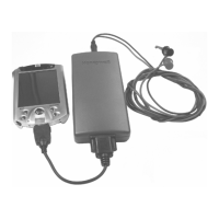
Introduces the MC Toolkit and SDC 625 software running on a PDA and highlights general-purpose features.
Provides a basic guide to using selected Pocket PC features with the MC Toolkit application software.
Illustrates the sequence for starting the Pocket PC and the MC Toolkit application software.
Explains the four PDA methods for character input: Block Recognizer, Keyboard, Letter Recognizer, Transcriber.
Explains how to navigate through MC Toolkit displays using menu buttons and the back button.
Details how to interpret and interact with various data fields and input boxes within the MC Toolkit interface.
Describes how to navigate the SDC 625 main screen using Device, View, and Help options.
Contains procedures for using MC Toolkit software to communicate with Honeywell DE Transmitters.
Summarizes the steps to access displays for Honeywell DE transmitters, including uploading data.
Details requirements for input calibration, emphasizing off-line procedures and precise sources for accuracy.
Explains output calibration procedures like Loop Test, Trim DAC Current, and Apply Values for proper transmitter function.
Guides users through the process of uploading transmitter data using the MC Toolkit.
Details the function of each menu item within the DE Main Menu for ST 3000 and STT 3000 transmitters.
Step-by-step instructions for calibrating the input of DE transmitters by setting zero, LRV, and URV.
Describes the Loop Test procedure to verify electrical components in the analog output current loop.
Explains how to calibrate the analog output current of a DE transmitter to 4 mA (LRV) and 20 mA (URV).
Details how to use actual process variable inputs to calibrate LRV and URV for DE transmitters.
Outlines the main menu procedures for Honeywell HART transmitters, covering device info and basic setup.
Explains how to access displays for HART transmitters and the role of the QUICK MONITOR.
Provides a summary of HART displays and their associated tasks, covering device info, setup, and calibration.
Step-by-step guide for initiating communication and uploading data from HART devices using the MC Toolkit.
Details the procedures available in the HART Diagnostics/Service menu, including Master Reset and Device Status.
Explains the Zero Trim procedure for Honeywell HART transmitters to adjust the zero reference point.
Provides instructions for calibrating the Lower and Upper Range Values (LRV/URV) of Honeywell HART transmitters.
Describes how to reset user input corrections to factory default values for Honeywell HART transmitters.
Details the Loop Test procedure to verify the integrity of analog output loop current in HART transmitters.
Explains the D/A Trim procedure to calibrate the analog output current of HART transmitters to minimum and maximum values.
Guides users on applying actual process variable inputs to set LRV and URV for HART transmitter calibration.
Introduces procedures for using SDC 625 software to communicate with any HART device.
Describes how to monitor Process Variables in engineering units, percentage, and analog output.
Details performing Loop Tests or D/A trims, and accessing Device Status and Write Protect functions.
Explains viewing and changing Tag, damping, CJ Temperature units, and Device I.D.
Covers configuration of Sensors, Signal Condition, Output Condition, Device Information, and Alarm settings.
Describes how to view device Model, Manufacturer, Device I.D., and software revision.
Lists common error messages encountered with MC Toolkit/SDC 625 and provides corrective actions.
Documents specific messages generated by DE transmitters and their meanings or required actions.
Lists error codes and messages specific to HART communication and device interactions.
Details critical and non-critical status messages for ST3000 transmitters operating in DE mode.
Lists critical and non-critical status messages for STT transmitters operating in DE mode.
Details critical and non-critical status messages for ST3000 transmitters operating in HART mode.
Lists critical and non-critical status messages for STT25H transmitters operating in HART mode.
Defines technical terms and abbreviations used throughout the MC Toolkit User Manual for clarity.
Lists fields and their corresponding values for configuring Honeywell DE transmitters via the MC Toolkit.
Provides a reference for fields and values used when configuring Honeywell HART transmitters.
Lists fields and values applicable to generic HART transmitters for configuration purposes.
Lists HART universal commands and their functions for interacting with HART devices.
Lists HART common practice commands and their functions for standard device operations.
Provides sample XML file structures exported from the MC Toolkit for DE and HART devices.
Explains when and how to replace the battery in the MCT101 modem.
Step-by-step instructions for safely removing and replacing the battery in the MCT101 modem.
Describes the pre-loaded software and hardware readiness of the MC Toolkit for use.
Explains how to use the DD Copier utility to place Device Description files into the MC Toolkit structure.
States that MCT202 battery is not field replaceable and directs users to customer support.
States that MCT202 SD card is not field replaceable and directs users to customer service.
Lists part numbers for MCT101 replacement components like the Pocket PC and DE/HART Modem.
Lists part numbers for MCT202 replacement accessories, docking stations, chargers, and cables.