Summary of Operating Procedures
Page 18 34-ST-25-20 MC Toolkit User Manual Release 3
9/06
Summary of Operating Procedures
To access displays for Honeywell DE Transmitters:
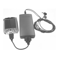
• Start the MC Toolkit application; the CONNECT TO ... display will appear. (Refer to Figure 8
Start-up - MC Toolkit Application.)
• Upload the database from the transmitter. (The QUICK MONITOR display will enable viewing of
key parameters before taking the time for database uploading.) The DE MAIN MENU appears. (Refer
to Figure 9 Menu Tree - Honeywell DE Displays in this section.)
• Select the appropriate display from the DE MAIN MENU. (Refer to Table 3 DE Main Menu
Procedures in this section, and to the list of DE displays .)
The content of each display is summarized in Table 1.
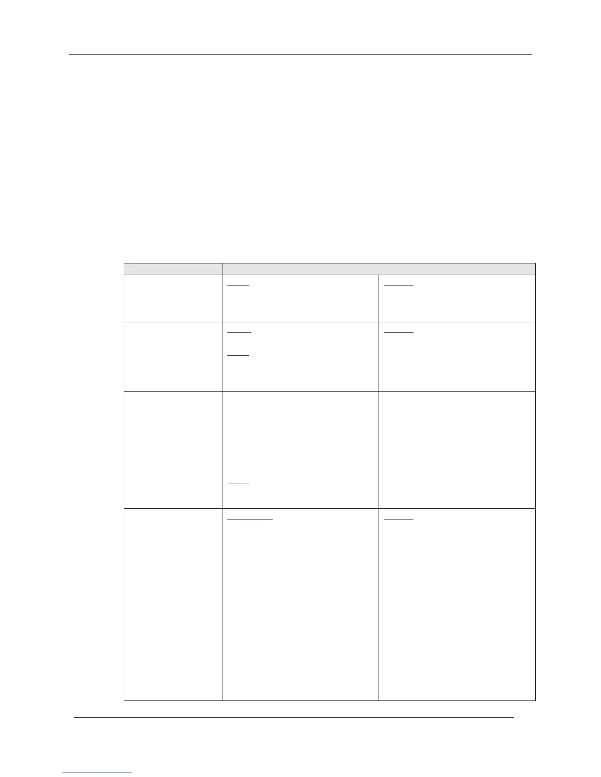
Table 1 DE Displays / Tasks Summary
Menu Item Task
DEVICE INFO
Enter:
Device Type:
• Tag ID
• Message (in Scratch Pad)
Observe (Read):
• Type
• Serial Number
• Firmware Version
GENERAL
Select:
• PV Type
Enter:
• Comm Mode
• Line Filter (STT)
• T/C Fault Detect (STT)
Observe
(Read):
• Failsafe Direction
DE CONFIGURE
Select:
• PV Units
• SV Units
• Conformity (ST)
• Damping
• Sensor Type (STT)
• Linear
Enter:
• LRV
• URV
Observe
(Read):
• LRL
• URL
• Span
• Sensor Type (ST)
CALIBRATION
Enter/Select:
• Correct Input (Zero)
• Correct Input (LRV)
• Correct Input (URV)
• Reset Corrects (Zero, LRV, URV)
• Loop Test (Check
• Trim DAC Current (Calibrate
output current)
• Apply Values (that is, re-range
LRV and URV to PV input)
Observe
(Read):
• Input at Zero, LRV, and URV
• (Verify) Reset Corrects
• Loop Current (continuity)
• Output Current level (at 0 %,
100%)
• Applied values of LRV and URV