Transmitter/Communications Characteristics
Page 4 34-ST-25-20 MC Toolkit User Manual Release 3
9/06
Transmitter/Communications Characteristics
The characteristics of a typical Honeywell Smart Pressure Transmitter are summarized in Figure 3 through
Figure 7, following.
Honeywell Transmitter (Analog Mode)
Analog-to-Digital Sensing
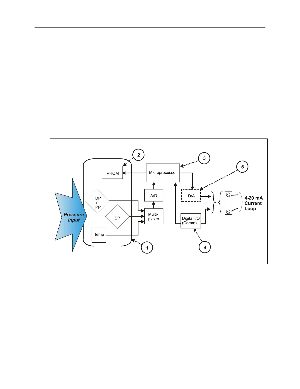
As indicated by key number (1) in Figure 3, the sensor is a sealed assembly that typically includes three
separate sensors: Differential Pressure (DP), Static Pressure (SP) and Temperature (Temp).
Input Characterization
The sensor also includes a PROM, (2), which is Non-Volatile Memory (NVM) that stores
"characterization" constants written at the factory, and calibration constants, which can be written at the
factory and/or at the user's site. The data in NVM is used in an algorithm in the microprocessor, (3), which
is executed continuously to calculate the input value.
Figure 3 Honeywell ST 3000 Smart Transmitter - Analog mode
The characterization constants, which are written at the factory, are derived from highly precise testing of
the sensor's response over a range of temperatures, and from the Lower Range Limit (LRL) to the Upper
Range Limit (URL) of the sensor. The purpose of the characterization constants is to compensate for very
small inaccuracies in the sensor that are introduced by variations inherent in construction materials, and to
ensure that the calculated input is a high-fidelity representation of the analog input (linear or square root),
with a precise "zero" reference.
Input Calibration ("Corrects")
To optimize accuracy, the PROM includes storage for calibration constants: Correct Input Zero, Correct
LRV, and Correct URV.
The corrects constants provide for optimum accuracy in that they enable fine-tuning of the input
calculations, by first correcting at zero input, then bounding the input calculations at the user's operating